Although this is appearing in the middle of the current series of loop signatures on digital controllers, I felt that it would be nice to have a change and write another article on some of the more interesting problems encountered in real life controls in plants.
At the conclusion of a particularly successful recent control course in a South African paper mill, which ended with two days in the plant optimising live loops, one of the delegates, a very senior instrument technician, remarked that previously he had had no idea whatsoever of the existence of the many problems we had found, because no other course had taught him how to uncover such problems.
This is very true. The reason we give these special courses is that very few people in the control field really understand the full practicalities of the subject. Many people have disagreed, and will disagree with this statement. One of them was the chief control engineer in a large plant with thousands of control loops, who when I first met him prior to our course, told me very emphatically that the basic loops in his plant had been optimised, and only 5% of them could be improved on. After the course, a new survey performed in conjunction with four of the plant's advanced control engineers was undertaken. On completion, some three months later, the same chief control engineer signed a report to top management stating that the new survey had revealed in fact, that a startling 68% of the control loops were completely ineffective in automatic.
I have on many other occasions also encountered similar changes in attitudes of highly experienced control engineers after they have gone through the training, and done some work in the plant. In fact, in most plants, senior control people and general management often share a general concept that the so called 'base layer controls' are working fine, and further that optimisation is merely a matter of tuning things a little better. They also seem to believe that optimisation is relatively simple and can be carried out by people with low skill levels. Unfortunately nothing can be further from the truth. In fact, after attending a course, the chief control engineer in a large South African petrochemical refinery recently remarked to me "Optimisation in this plant is now only performed by the best and brightest of my control engineers."
Going back to the course in the paper mill mentioned above, I would like to illustrate a couple of the fairly startling problems we uncovered in an important control loop. Previously, in spite of quite a few attempts to optimise the loop, no one had any idea of the existence of these problems. The loop in question was the temperature control on the vacuum condenser on one of the drying sections on one of the paper machines.
Good moisture control is very important in the papermaking process, so all the loops that make up the drying section control should be really well optimised. On this particular machine, one of the controls was a temperature controlled by varying the flow of cooling water into a heat exchanger to condense the steam. Those at the plant knew that the control performance on this loop was bad, and many attempts had been made over the years to tune it better. The control loop consisted of the temperature signal (PV) being fed into the controller and the output of the controller (PD) being sent directly to the cooling water valve. (A subject that will hopefully be covered in some future article is the need for 'perfect valves' for good control of processes with slow dynamics, such as temperature.)
It will be shown there that if the valve has problems like hysteresis, nonlinearity, and poor rangeability, then it can literally take hours on a slow process for the controller to get the valve to settle at the right position. Perfect valves are rarely found in reality. To overcome the problem, and turn an ordinary everyday control valve into an almost perfect one, you have to make use of a cascade flow slave loop, so the primary temperature controller, requests the slave to supply a certain quantity of water, as opposed to having to infer this by directly trying to position the valve.
Remember that the primary controller is set up to deal with a rather slow temperature process, and is therefore tuned relatively slowly, which is why it would take so long to correct valve problems. The cascade secondary flow loop on the other hand is dealing with a fast flow process and is tuned really quickly, and thus can sort out the valve problems within a relatively very short time, and will supply the correct amount of water as asked for by the primary controller.
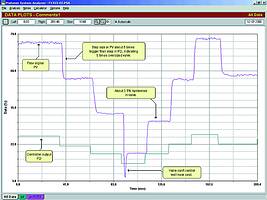
Fortunately in this particular case, although there was no cascade secondary loop installed, there was a flowmeter in the cooling water line, so the first test performed was making steps in manual on the output of the temperature controller, recording both the water flow and temperature. Figure 1 illustrates the recording of output and water flow.

A major problem was revealed by this test: The valve was some five times oversized! Generally one can tolerate a valve that is up to twice oversized, but five times oversized can only lead to problems. The problems that can be encountered with oversized valves were discussed in a fairly recent loop signature dealing with process gain. One of the problems is that extremely small proportional gains will be needed in the controllers on fast loops like flow loops. In this case, to control the flow (when a cascade secondary control was inserted - see later), the gain in controller was tuned to a tiny value of 0,03! (Many controller manufacturers limit their low-end range of gain to 0,1.)
However, the main problem with the oversized valve in this case, was that in the normal control region the valve often had to operate fairly close to its seat. Figure 1 shows how unstable the valve is at an opening of 15%. (Control valves do not work well near the seat. As a rough rule of thumb, under normal control conditions, the valve should be operating above 20%.) In addition, a second problem was uncovered by the flow test, and that was the valve suffered from close to 3% hysteresis. (Maximum acceptable hysteresis on a high quality control valve is about 1%).
These two problems were not easily apparent before tests were done using the flow as an indicator of valve performance. It would have been very much more difficult to pick them up by testing the temperature response directly from valve movement. With severe valve problems such as these, good control could never be achieved if the temperature controller was coupled directly to the valve, so it was decided to immediately implement a secondary cascade flow controller into the temperature control system. The faster flow controller would be able to deal with the valve problems far more swiftly, and ensure the correct volume of water was supplied as requested by the temperature controller for cooling.
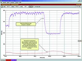
Figure 2 shows a tuning test performed for the temperature controller. The steps on water flow (which was in automatic) were following step changes made on the output of the temperature controller, which was in manual. The test uncovered yet another problem - the temperature transmitter was some 10 times over-spanned - which again does not make for good control. (See recent loop signature.)

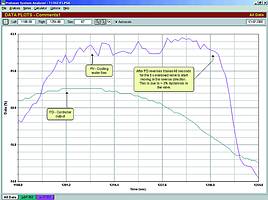
The effects on the final control of these various problems can be seen in the next two figures, which are taken from a final closed loop test on the final system. Figure 3 shows a section of the test where the temperature controller is calling for less cooling water, and the flow controller is trying to reverse the valve. As can be seen, it took some 40 seconds before the oversized valve could actually start moving. This was due to the 3% hysteresis in the valve, as the output of the controller has to integrate right through the hysteresis band every time the valve has to be reversed.

Without the cascade loop the temperature controller, with its much slower integral setting, would probably have taken well over half an hour to get the valve to reverse.

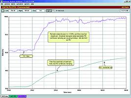
Another interesting problem revealed by the test is shown in Figure 4. The temperature setpoint had been stepped up. The temperature controller's output immediately asked the flow controller for 100% maximum flow. The flow moved up to just under 100% of the measurement range and stayed there - probably because of the calibration of the flow transmitter. However, it did not quite get to 100% where the setpoint was. The PD (controller output) at maximum flow was about 40%. Therefore, the flow controller's integral action still carried on ramping the valve even further open. This could have continued until the valve had reached full opening at a PD of 100% - at which stage the controller's anti-reset windup would have switched on and frozen further integral action. Now, when the temperature reached setpoint, the temperature controller would instruct the flow controller to cut back on the flow. However, the flow controller could not even start reducing the flow until the valve opening had been reduced all the way back to 40%. This could cause severe overshoots in the temperature. Again it would have had devastating effects without the cascade control.
This is another nice example of a potential severe problem that can occur with oversized valves. It is of interest to note that it is very good practice on every oversized valve to insert a high limit on the controller's output at the point where further valve opening can produce no further increase in flow. This will prevent the valve moving into a region where it can have no further effect on the process and also prevents the integral winding up. The problems encountered in this apparently simple temperature control loop are good illustrations of the various problems that can and do occur in control loops, and of which nobody in the plant is aware, because they have not had the training to analyse such problems.
Michael Brown Control Engineering
(011) 486 0567
Michael Brown is a specialist in control loop optimisation, with many years of experience in process control instrumentation. His main activities are consulting, and teaching practical control loop analysis and optimisation. He gives training courses that can be held in clients' plants, where students can have the added benefit of practising on live loops. His work takes him to plants all over South Africa, and also to other countries.
| Email: | [email protected] |
| www: | www.controlloop.co.za |
| Articles: | More information and articles about Michael Brown Control Engineering |

© Technews Publishing (Pty) Ltd | All Rights Reserved