
Incorrect perceptions result in poor control.
There is no doubt that one of the main reasons why the vast majority of regulatory control loops perform so badly is a general lack of understanding of the principles of practical control. In my view, this admittedly harsh comment, applies pretty much across all disciplines in the plant including process specialists, operators, and even C&I (control and instrumentation) managers, engineers, and technicians, who top management expect to have the requisite knowledge and skills.
Putting theory into practice
The reason for this, as I have mentioned many times before, is a lack of practical training to complement the theoretical control theory taught in most educational institutions. The basic theory is brilliant, and I am a great admirer of mathematicians like Bode, Nyquist, and Nichols who developed it using purely their mental prowess in the days before there were control systems as we know them. However it needs to be supplemented with practical training if it is to be useful in real world control applications, which have to deal with the horrors of mechanical final control elements, non-linearity, noise, and many other factors that the theory does not, and really cannot, take into account.
This basic lack of understanding causes people to develop their own ideas of control which are very often wrong. Typical examples of incorrect perceptions are:
* Any problem can be solved by tuning.
* Computerised control and instrumentation equipment must be right because a computer is involved. Furthermore computerised systems do not need skilled people to use them, and set them up correctly.
* Smart positioners eliminate all valve problems, as they also contain a computer.
* Similarly smart transmitters must give correct PV values.
* If loops operate in automatic then the control is good.
* The control is good if the trends are nice straight lines.
* Feedback control systems should be able to eliminate variance completely irrespective of dynamics in the process and load changes.
* Feedback control systems should be able to eliminate variance completely, both on the input and output of the process.
* If the output of the controller moves around a lot it is bad. (In fact many continuous process control performance monitoring packages incorporate a feature called ‘valve travel index’ (VTI) to measure this. However, often no account is taken of load changes, so if the VTI is too high, the controller is often detuned.)
Is the trend always your friend?
I recently spent a few days in a mining processing plant where the control performance was judged purely by examining trend lines. If there was no cycling then the controls were deemed to be fine. When I pointed out that all the flow loops were ‘tuned’ almost into manual and could not respond properly to changes, I was not believed until we made some set-point changes. Controls are there to minimise variance under changing conditions. In cases where the plant is running in steady state, and provided there is a little bit of gain and some integral set in the controller, then the process will eventually get to set-point and stay there, as nothing is changing.
In reality operators set up the controls in manual, and when they get the process to the desired operating set-point, they switch to automatic. If nothing changes after that then the process stays there and the trends are beautiful straight lines.
What happens if there is a change, which could be either a set-point change, or a load disturbance? In most real life cases the controls are set up so slowly that the controller cannot deal with the change in automatic, so the operators immediately switch to manual, and adjust the controller’s output to get the process back to set-point. They then switch back to automatic.
To illustrate the case in point, all the flow control loops at this particular plant had been set up with an integral value of 60 seconds. As the integral value for self-regulating processes should be set equal to the time constant of the process, an integral value of 60 seconds for the average flow loop immediately informs one that it is about 30 to 60 times too slow, and there is no way that the control will be able to cope effectively with changes.
The comparison in tuning is illustrated dramatically in Figures 1 and 2. In the first figure one can see the response to a 10% set-point change on one of the flow loops with the existing ‘as found’ tuning. The process had not even reached the new set-point a half an hour later. With the correct integral in the tuning, and a gain that allows effectively critical damping, which is considered a fairly slow and extremely robust tune, the process gets to set-point in about 30 seconds after the same change. This is shown in Figure 2.
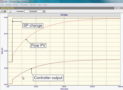
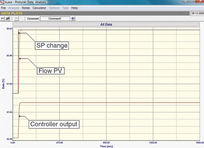
The control people in the plant had always considered that their flow loops were working extremely well! However, the tuning was in fact useless. As they only looked at trends when the flow process was stable, they saw everything steady on set-point with no cycling so they were happy. In fact one could say that they may just as well have left all their flows in manual. What is the point of using expensive control equipment that is not actually working properly?
Their main concern was the control on the floatation bank levels, which far from being stable were cycling in the extreme.
The problem with floatation banks
A previous case history No. 105, dealt with some aspects of floatation bank flow controls. However the control of the level in each cell is also critical. Figure 3 shows a typical bank with only four cells, but most banks in platinum concentrators contain many more cells. Additionally, the output from some of the banks can also be fed into others further downstream. The level in each cell is monitored by a level transmitter, (usually ultrasonic), and this PV signal is sent to a level feedback controller which modulates one (or sometimes two) parallel valves on the output of the tank. The output flow from the cell then gravitates into the next tank, and so on down the line.
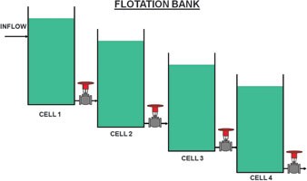
A future case history will be dedicated only to discussing the problems associated with the level control of floatation banks. However, for the moment, suffice it to say that there are in fact numerous problems which make this particular type of process extremely difficult to control, and it is extremely hard to achieve accurate control and keep levels in cells constant. One of the main problems which I wish to discuss here is that the levels in the cells throughout the banks tend to be cyclic.
Levels are integrating type processes which for all the reasons detailed in my Loop Signature Series are inherently unstable and tend by nature to be cyclic. Now it is obvious that if the feed into the first cell in a bank is not constant, then the feedback controller will react and will adjust the valve on the cell’s output, which in turn will cause the feed into the next cell to also vary. This will repeat all the way down the bank.
A problem that will be explained in the future article is that an unstable or non-constant feed into the bank will almost certainly result in cycling, which will probably occur in all the cells in the bank. Unfortunately, again for reasons that cannot be dealt with now, the feedback level control of floatation bank cells generally has to be pretty slow, and it is almost impossible to keep the levels constant if the flow through the bank is continually changing. What generally results is an amplifier effect with a smallish cycle in the first cell getting larger and larger as you progress down the bank.
Now the view of the metallurgists in this particular plant, a view I have found in many other plants as well, is that there are level controllers in each cell and it should be a simple matter to tune them properly and eliminate cycling completely.
While it is completely true that the reason for applying controllers to continuous process plants is to minimise control variance on each process, the unfortunate reality is that control cannot make the variance vanish completely. All the controller does, in fact, is transfer the variance from the measurement (output) side of the process to the other (input) side of the process. This is nicely illustrated in Figures 4 and 5. So although one may be able to try and keep the level fairly constant in the first cell of the bank by using the best and fastest possible tuning (which unfortunately as stated above, is not all that fast), the variance is immediately transferred into the second tank, and because of the dynamics of the processes, and the tuning, it usually actually increases the variance in the next cell – hence the amplifier effect.
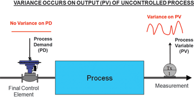
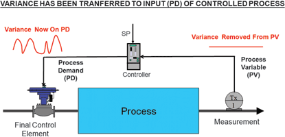
Feedback control cannot deal very effectively with this problem. Therefore the most essential thing in this type of process is to ensure that the feed into a floatation bank is kept as steady and constant as possible. To achieve this, it is necessary to absorb fluctuations in feeds occurring upstream in the process by installing a surge tank situated immediately before the bank. This tank must be sized large enough to allow a constant feed to into the bank under all load conditions. The surge tank has to have a special level control applied which keeps the tank from overflowing or running empty but at the same time tries to keep the output flow as constant as possible; and if and when it does change, then the change must be very slow. The best way of achieving this is to use an ‘error cube’ technique which has been described fully in Loop Signature P1-29 (available on CD for persons outside South Africa). (The next case history due for publication in two months, will also be discussing more aspects of this.)
Once the flow into the first cell is nice and steady, then the feedback control can deal happily with the level, and does not have to keep on making variations which would affect the next cell, etc. Unfortunately this plant had been designed and built without any surge tanks, so most of the banks in the plant were nearly always cycling badly. To compound the problem, the outlet of some banks is fed into the input of other banks, and the outlet of certain banks is also recirculated into the same bank. These feeds, which of course are now very cyclic, compound the problem dramatically, and there is very little chance that any simple fix, such as tuning, can be made. Unfortunately, the general impression of personnel in the plants is that all that needs to be done is to better tune the controllers.
Conclusion
It should be mentioned that various more advanced techniques such as feed-forward control systems can be used to try and minimise the problem, but these generally are not all that successful, as dynamics and conditions change with time and loads, and the dynamic models used then no longer work well. One plant metallurgist I worked with some time ago, said that her advanced control floatation bank level control system worked well provided it was completely retuned at least once every six weeks. This would not be so critical if the basic things like surge tanks to ensure constant feeds were incorporated, which would then allow the base layer controls to work properly.
If the plant designers and process experts only had better understanding of the principles of practical process control, they would be able to design and get their plants to operate much better with vastly increased recovery rates, and far fewer problems. In my opinion the primary obstacle to achieving this is the misconception about the operation and capability of control.

Michael Brown is a specialist in control loop optimisation, with many years of experience in process control instrumentation. His main activities are consulting, and teaching practical control loop analysis and optimisation. He gives training courses which can be held in clients’ plants, where students can have the added benefit of practising on live loops. His work takes him to plants all over South Africa, and also to other countries. He can be contacted at Michael Brown Control Engineering, +27(0)11 486 0567, [email protected], www.controlloop.co.za
| Email: | [email protected] |
| www: | www.controlloop.co.za |
| Articles: | More information and articles about Michael Brown Control Engineering |
© Technews Publishing (Pty) Ltd | All Rights Reserved