
The elements of a control loop normally consist of the process itself, the measuring transmitter, the controller and the final control element. The latter, in the vast majority of loops, consists of an I/P (current to pneumatic) converter and a pneumatically actuated valve, generally fitted with a positioner.
Some theoretical background
Good modern transmitters are engineering masterpieces based on decades of scientific research and knowledge and enhanced with the latest in microcomputer technology. They are generally reasonably, if not highly, accurate, and usually very reliable.
Most PID controllers today are simply blocks of software inside a modern computer that operates extremely accurately. NB: Said controller software is based on fantastic feedback control theory perfected by three of the world’s greatest mathematicians about 80 years ago.
The controller compares the desired operating setpoint (SP) as set by the operator, or by a higher level advance controller, against the actual process variable (PV) and performs a mathematical calculation. The result of this sets the value or amount of product that should be fed into the control loop to bring the PV to setpoint and result in zero error.
Unfortunately the controller can only output this result (PD) as an arithmetic value normally given in percentage terms between 0 and 100%. This by itself can obviously not control a physical thing like a flow of product. Therefore, the final item in the control loop, sometimes called the final control element, is used to translate the PD value into the control of a physical phenomenon such as flow. The final control element, referred to as the valve hereafter, should be thought of as a ‘translator’ or slave element that does the controller’s bidding. This leads to the maxim: ‘The more accurately the valve carries out the controller’s demand, the better will be the control’.
And a bit of practical advice
Herein lies the rub! Whereas the transmitter and the controller are items operating close to perfection, the valve is normally a mechanical device. Mechanical devices can be a host to all sorts of problems including friction, excessive stick-slip, hysteresis, non-linear characteristics, corrosion, insufficient actuation power, limited range and many other things. Even on more sophisticated control elements, variable speed pumps for example, there are a whole bunch of inherent physical problems that limit their performance. As a result about 80% of problems associated with control are found to fall within the valve area of the loop. Typically a full third of my three day control course is devoted to problems with final control elements and the diagnosis thereof.
Many of these problems can be dealt with fairly simply using techniques that can be incorporated into the control philosophy and sometimes into the tuning. In fact, in most cases, it is not necessary to shut down the loop in order to physically work on the valve. These techniques generally allow the loop to carry on operating until a more convenient time arises to make proper repairs to the valve itself.
Let us consider some exceptions
Unfortunately, in certain cases there are problems where the valve is so bad that good control becomes impossible – in these cases it is necessary to fix or replace the valve. The two worst cases are when the valve is non-repeatable and basically ‘does its own thing’ irrespective of the controller’s dictates, and secondly, if it causes cycling. Two cases of really bad valves like these are the subject of this month’s article.
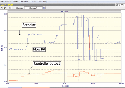
The first example shows one of the worst valves I ever encountered in a plant. Figure 1 is a recording of a closed loop test performed on a flow control loop. The flow is at setpoint, but, after a step change is made, there is a relatively long period where the PV does not change because the valve is stuck. The graph of PD shows how the controller’s integral action is ramping up the output. Eventually the valve breaks away and the flow comes back fairly close to setpoint. It stays there for a while looking quite good, then suddenly, and for no apparent reason, the valve jumps down and the flow drops. The controller tries to correct and you can see the PD ramping up again. The valve sticks for a while and then breaks free and jumps too much and the flow goes up way past setpoint. The controller tries to bring it back, but then the valve goes unstable and jumps up and down.
An open loop test was then performed and is shown in Figure 2. It shows some remarkable things:
1. Steps of the same size on the PD result in steps on the PV the size of which differ frequently, being particularly different when the valve is opening as to when the valve is closing.
2. On many steps, but not on all, there is a huge overshoot and recovery (sometimes much bigger than the actual step size) when the valve moves.
3. The overall changes in PV compared with the overall changes made on the PD are much larger than unity, indicating that the valve is probably largely oversized.
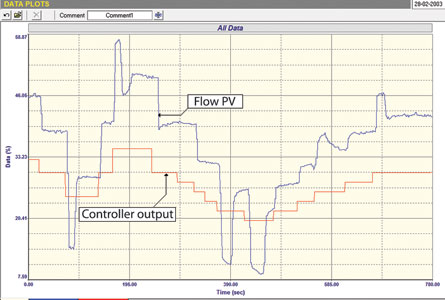
These findings show that control is really impossible with this valve. Basically it is too non-repeatable and the overshoots will (and did) result in instability when running the controller in automatic.
It was later found that the valve positioner, one of the modern ‘smart’ variety, had never been set-up properly. A representative from the manufacturer was called in to do this and good control was then attained.
This is an interesting point as I have come across many people who believe that all their valve problems will be eliminated if they use smart positioners. Whilst I fully agree that a good modern smart positioner should operate much better and more accurately than the old type of mechanical-pneumatic type of positioners, which have been around for many decades, the modern units need proper commissioning. One must always remember that they contain their own feedback (usually P+I) positioning controllers that act as a cascade secondary to the main loop controller. Therefore, they must be properly tuned taking the rules of tuning cascade secondary controllers into account.
The second example is also flow loop where the valve was very bad. The closed loop test displayed in Figure 3 shows the operation with original ‘as-found’ tuning with a step change of setpoint being made. The first thing that can be seen is that the tuning is woefully slow for flow control with the integral being set too big (ie, too slow). However, when watching the response of a fast process like a flow loop, one of the advantages of too slow an integral is that the slow ramp allows one to get a good idea of how well the valve follows the PD. In this case one can see that the valve is very sticky and then it slips and sticks again. This is very bad.
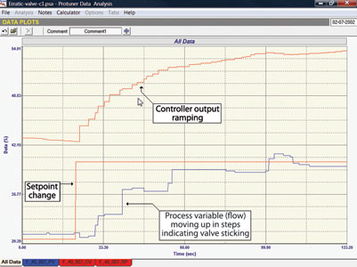
Figure 4 shows the open loop test on the same loop with various steps of the same size had been made on the PD. It can be seen that the PV did not respond consistently with some steps being of different sizes, in a couple of cases there was also some overshoot. This again shows non-repeatability and non-consistency of valve response that can only cause problems with the control. However, it is not nearly as bad as the valve in the first example, so it might be possible to get more or less acceptable control using better tuning with a small proportional gain and relatively fast integral set as close as possible to the dominant time constant of the process – the idea being to get the valve moving as smoothly and ‘bumplessly’ as possible when control deviations exist.
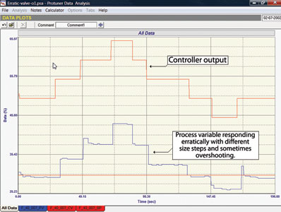
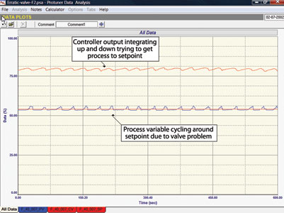
Figure 5 shows the final closed loop test with the setpoint being held constant. The PV is pretty close to setpoint with a strange little ‘stick-stick’ cycle occurring on it. This is quite interesting: what is happening is that the valve sticks close to setpoint. One can see on the PD that the controller output is ramping under the integral action to get the valve away, but once it moves it overshoots, and the controller moves the valve back down again. This is repeated ad-nauseam. Provided that there is no interaction with another loop this little cycle is not serious and will not do any harm.
In conclusion my message: In both of the above cases, nobody in the plant diagnosed the problems as valve related. People were trying to sort out the problems by playing around with controller tunings.

Michael Brown is a specialist in control loop optimisation, with many years of experience in process control instrumentation. His main activities are consulting, and teaching practical control loop analysis and optimisation. He gives training courses which can be held in clients’ plants, where students can have the added benefit of practising on live loops. His work takes him to plants all over South Africa, and also to other countries. He can be contacted at Michael Brown Control Engineering cc, +27(0)11 486 0567, [email protected], www.controlloop.co.za
| Email: | [email protected] |
| www: | www.controlloop.co.za |
| Articles: | More information and articles about Michael Brown Control Engineering |
© Technews Publishing (Pty) Ltd | All Rights Reserved