

Noise on the PV signal was discussed in the previous loop signature article, and it was mentioned that it is generally better to live with the noise rather than filtering it out; provided it does not cause the final control element to jump around excessively. This article explains this reasoning.
Normal filters used in process control have a first order lag type dynamic, which is generally preferable to time averaging filters. This is because PID controllers can handle lag dynamics better. A lag type filter is also referred to as a low pass filter, as it passes the lower frequencies and attenuates higher frequencies components. Visually the filtered signal appears to have less noise. Obviously the higher the filter constant value, the smoother the output signal.
In the old analog days, filters were very difficult to implement, and as a result were seldom used. Today it is very easy to implement a simple lag type filter on a digital control machine. Only a few lines of code are needed. Most DCS, and a few PLC manufacturers offer filters as a standard block. These filters usually allow one to insert lags in a loop ranging from fractions of a second to literally hours. When a filter is used in the control equipment it is usually inserted before the controller and the operator's display, or scada.
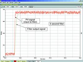
Figure 1 shows the response of a flow signal to a step change on the PD (controller output). The signal has noise of some 2% amplitude on it. The signal is then passed through a filter with a 5 s time constant, and the output of the filter is shown in the same figure superimposed over the original PV signal. It can be seen that the noise amplitude on the filtered output has been reduced considerably. There are still some fluctuations due to the lower frequency components present. Apart from that, the signal has not been changed drastically.
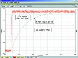
In Figure 2 one can see how the situation has changed when a 50 s filter is used. The noise has now been completely eliminated. The filter has certainly achieved its purpose insomuch as it has got rid of the noise. However, the signal response has been drastically slowed down. The filter has now replaced the flow process as the dominant dynamics in the control loop. In other words we are now trying to control a filter rather than a flow!
Many learned texts on control have stated that if the time constant of the filter exceeds the dominant time constant of a self regulating process the control will be adversely affected. This is not necessarily correct, as you will see in the next example. Tests we have performed show that you can in fact get quite reasonable control on loops with relatively heavy filters. However, there are other really serious effects that are more important, and which make the use of big filters very undesirable. One of these seriously bad effects is that filters can cause excessive PV overshoots (as high as 300%), on step-changes in setpoint. Such an overshoot is shown in the next example.
In previous articles I have also referred to filters as the world's biggest liars, as they can distort the response of the process as seen on scada or DCS screens by the operator. The filter actually tends to reverse the facts, making good things look bad, and bad things look good!
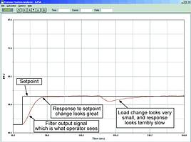
To illustrate this point, Figure 3 is the recording of a control system on a noisy process. The controller has a filter with a 50 s time constant in it. The controller is well tuned. The recording is made with the Protuner analyser connected at the input to the controller (upstream of the filter). A 10% step change in setpoint is followed by a 10% step change in load. An enormous overshoot on the PV response to the setpoint change can be seen. It is really bad. The load change however is controlled well. The controller brings the process back to setpoint speedily with little overshoot. This is in fact really good. (It also shows you can indeed get quite good control even with a big filter.)
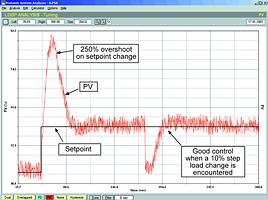
Figure 4 shows what the operator sees on his screens with a filtered signal. The setpoint change looks really good. There is no sign at all of an overshoot. However, the load change now looks terrible. It only shows as a tiny offset, which seems to take forever to get back to setpoint. Therefore, the filter has completely distorted and reversed the true facts. This is to me the most dangerous thing of all, as the operator does not really know what is going on in the plant.
It must be remembered as well that the people doing the tuning are generally also unaware of what filters can do, so they often ruthlessly eliminate noise with enormous filters, and then do tuning whilst looking at the filtered signal, so they have no real idea of the true response.
It is common practice these days for management to use the information available on the scada for management evaluation and control purposes. Therefore, it is vital that people should avoid using big filters if they want to have reliable information. This was illustrated on a mine in southern Africa where all the plant accounting and management information was based on a transfer from their scada package into spreadsheets. Large filters were applied on nearly every loop. The metallurgists found that they were faced with a never-ending puzzle as to why the plant balances never seemed to work out.
Rules for filtering
Sometimes one has to apply filters when the noise is too much and starts moving the final control element around too much. If you apply the following 'rules of thumb' you will find that you cannot go too far wrong.
* If possible, eliminate the noise at its source.
* Use an anti-alias filter on the transmitter. (To be discussed in a future loop signature).
* Try tuning without a filter and check at the actual valve if it is moving due to the noise.
* Avoid using filter constant values larger than necessary.
* Largest filter constant value <10 x (process deadtime + scan rate of controller).
* Use I-PD controller with filters. (See Loop Signature No 16).
* Train the operators and process people about filter effects.
The last point is one of the most important. Unfortunately process personnel are so used to heavily filtered signals in most plants, that they get very unhappy when filters are removed. As mentioned in the last loop signature, they mistake noise for instability. It is sometimes very hard to convince them that the control has in fact been significantly improved.
It was mentioned earlier that if you do have to use a filter, then it should be inserted in the control equipment rather than the transmitter. This is because you cannot see the control response at all if you filter in the field. The one exception to this rule is an anti-alias filter, which will be discussed in a future Loop Signature article.
For more information contact Michael Brown, Michael Brown Control Engineering, 011 486 0567, [email protected], www.controlloop.co.za
Michael Brown is a specialist in control loop optimisation, with many years of experience in process control instrumentation. His main activities are consulting, and teaching practical control loop analysis and optimisation. He gives training courses that can be held in clients' plants, where students can have the added benefit of practising on live loops. His work takes him to plants all over South Africa, and also to other countries.
| Email: | [email protected] |
| www: | www.controlloop.co.za |
| Articles: | More information and articles about Michael Brown Control Engineering |


© Technews Publishing (Pty) Ltd | All Rights Reserved
 printer friendly version