The operators in a petrochemical refinery were having great trouble in trying to stabilise the condensate level in a vessel, as it was adversely affecting other loops downstream. Several unsuccessful attempts had been made to retune the controller.
Level processes almost always fall into the integrating class of processes, which have been described in several previous articles, the most recent being in Case History 194, published a couple of months ago, so I will not repeat the basic description of the characteristics of these processes. However, it was mentioned that the PV of an integrating process, like level, will remain constant when the input and the output of the process are of equal value, and that the value of the controller’s output (PD) at that point is referred to as the Balance Point. When one changes this value of the PD by a step, the Process Variable (PV) starts moving in a constant ramp.
Should we step the PD back to the previous Balance Point, the process should once again balance out and the PV should then stop ramping and remain constant at the value where it had reached. If it does not remain constant and continues ramping, likely at a different ramp rate, then one or more of the following things would have occurred:
• The valve did not move back to the correct position due to positive or negative hysteresis.
• There was a load change in the process so the balance point changed.
• The process itself was non-linear, examples of which would be measuring levels over nonlinear regions, for example in a horizontal cylindrical vessel like a boiler, or a gravity feed vessel where there is no pump on a bottom outlet.
The balance point changes all the time as the level increases or decreases.
When we came to do the testing on the loop, we did indeed find that the level was cycling slowly with the controller in automatic. Continuous cycling in integrating processes is generally due to one of the following causes:
• Positive valve hysteresis plus the use of the integral (I) term in the controller.
• Negative valve hysteresis.
• Bad tuning.
Bad tuning of integrating loops is mainly due to incorrect settings of the I-term, as most people do not have a ‘feeling’ or understanding of how to tune integrating process controllers correctly. It is generally very difficult to cause instability in the majority of integrating processes by using too high a proportional gain (P). This particularly applies to levels which generally have a quite large retention time. I have found that most people tend to not use a high enough gain on integrating processes to get a reasonable response in automatic.
This is very different to the tuning of self-regulating processes, particularly fast ones like flows, where too high a P-gain can easily cause instability. I have found that most practitioners have a better feeling when it comes to tuning self-regulating processes, and don’t fully comprehend how to go about tuning integrating processes, which require a completely different mindset.
If an integrating process is cycling due to one or both of the reasons listed in the points above, one can easily stop integrating processes from cycling merely by switching off the I-term, and the D-term, if utilised. The process should stop cycling and find its balance point. This may not leave the PV at set point, but this does not matter when running tests.
The equivalent of a P-only controller on level control is the very ancient method of using a mechanical ball valve to keep the level constant. These do not cycle.
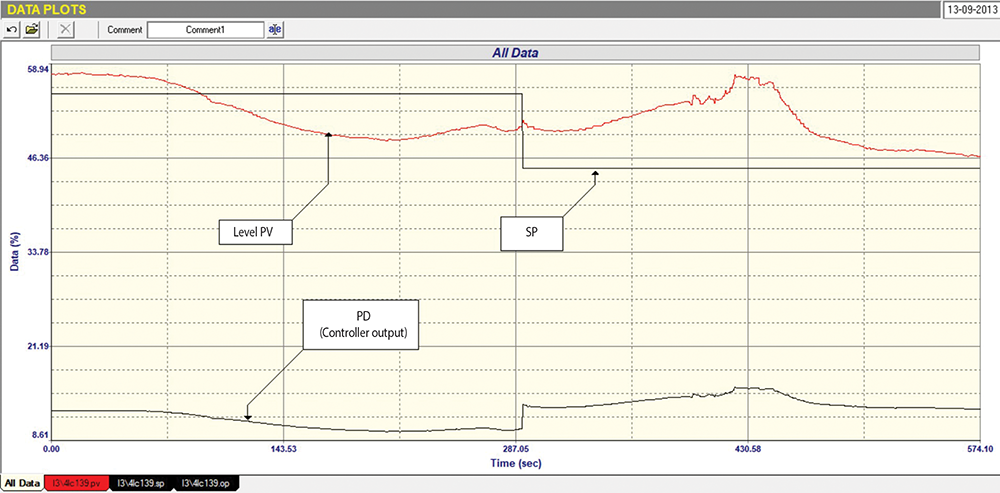
Tests were performed on the condensate level. The first was a closed loop As-Found test, which consisted of running the loop in automatic without changing any settings. This test is shown in Figure 1. It was seen that the loop was cycling very slowly around the set point. The set point was then stepped down by 10%. This appeared to have very little effect on the PV for quite a long time. The level did then move down slightly, but continued cycling.
Please note that the original tuning was P = 0,3, and I = 10 minutes/repeat.
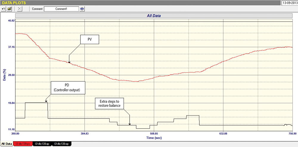
An open loop test needed to be performed next. However, the test could be conducted, it was necessary to stop the cycling and find the balance point on the PD. The Integral term was switched off, but the loop was so slow in responding, it was decided to change the P- gain to an arbitrary value of 2.0. This worked well, and the process came down to balance quite quickly, with the balance the test performed, shown in Figure 2.
The value of the PD at the balance point was 15,13%. Assuming valve calibration was correct, this is quite low down, indicating the valve operating in a very small opening, and that the valve was likely oversized. A well-known general rule of thumb is that control valves, under normal operating conditions, should operate above a 20% opening, as various problems can occur if a valve is trying to close in too closely to the seat.
One of these problems can be in machining the valve parts correctly, so the inherent valve characteristics are still followed at low openings. Another problem is that differential pressure across the valve could have increased, and in some cases the actuator may not have sufficient force to overcome this pressure, resulting in the valve cycling open and shut.
Once the process was in balance, the PD was stepped up by 5%. The process responded with the PV dropping at a nice constant ramp. The PD was then stepped back to the original balance point. If all was working correctly, the PV should have levelled out, but it continued ramping down, although at a much slower ramp rate. As discussed above, this could have been caused by a load change, by positive valve hysteresis, by non-linearity in the process or in the valve characteristics.
The PD was then moved down in small steps of 1% in an attempt to restore balance. However, after closing it, it is down by 3%, the PV started ramping up again, and this time it took 4 x 1% steps in the opposite direction to restore balance. The PD was then stepped down again, and the PV started ramping up. After a while the ramp rate started dropping off slowly, most probably due to a load disturbance occurring, which would change the balance point.
Just out of interest - this type of thing makes testing of integrating processes incredibly challenging at times, as plant conditions change frequently in integrating processes, for example levels. For this reason, it makes life so much simpler to do the testing if you can record the flow though the valve. This allows you to actually see what the valve is doing. I always recommended that, if possible, a portable flow meter like a clamp-on ultrasonic flow meter be used if there are no flow meters installed in line with the valve. It can save a lot of time and likely result in cost savings by allowing integrating processes to be accurately analysed.
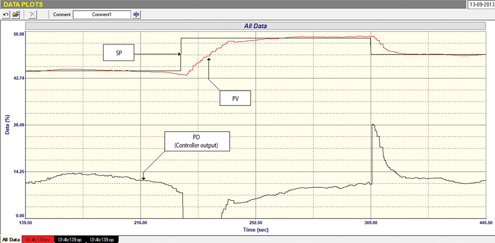
The present case the test allowed us to calculate reasonable tuning parameters on the two ramps that we could use after the valve had been stepped. The new tuning we decided to use was P = 3.4 and I = 0.9 minutes/repeat, which is a huge difference from the original tuning of P = 0.3 and I = 10 minutes/repeat.
It is of interest to note that the open test allowed us to determine the retention time of the level, approximately 27 seconds, translating to the process being quite fast. As a general rule of thumb, level processes with retention times with 10 seconds or less are regarded as fast and can be quite difficult to control, especially if the dead time (DT) is significant. To keep in mind, the DT should be less than a tenth of the retention time on integrating processes. The dead time in this case was about 2,3 seconds, with the controllability was just on the limit, requiring precise tuning.
The final closed loop test with the new tuning parameters is shown in Figure 3. It can be seen that the control is now working pretty reasonably. The response is fast, although a certain amount of cycling can still be expected because of the valve problem. However, the control could now react fast enough to keep the PV at set point. It is an excellent example of how bad tuning and valve problems can result in cycling.

About Michael Brown
Michael Brown is a specialist in control loop optimisation, with many years of experience in process control instrumentation. His main activities are consulting and teaching practical control loop analysis and optimisation. He now presents courses and performs optimisation over the internet. His work has taken him to plants all over South Africa and also to other countries. He can be contacted at: Michael Brown Control Engineering CC,
| Email: | [email protected] |
| www: | www.controlloop.co.za |
| Articles: | More information and articles about Michael Brown Control Engineering |


© Technews Publishing (Pty) Ltd | All Rights Reserved
 printer friendly version