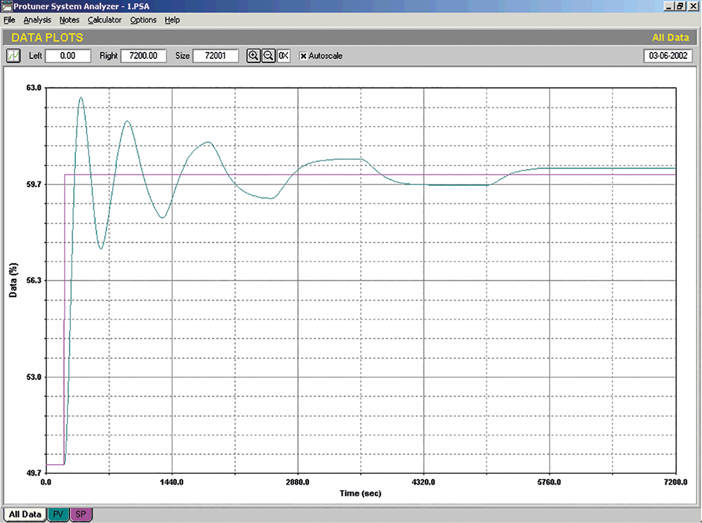
People often have little realisation as to how badly a faulty valve can affect the performance of the control of the loop. Figure 1 shows the response of a slow temperature control loop to a setpoint change. In the test, taken over nearly two hours, the loop has still not stopped cycling. It looks like it has been terribly badly tuned. However, at the time of this test it was determined that the control valve suffered from a hysteresis of 6,8%, which is extremely bad
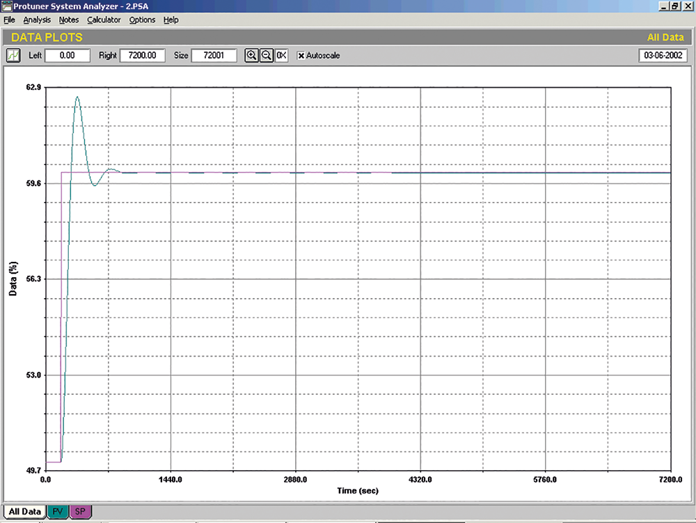
Figure 2 shows the response of the same loop after the valve had been replaced with a good one. What may be hard to believe is that the tuning has not been changed at all since the previous test. On the setpoint change, the process reached the new setpoint and settled out quickly within a few minutes. All the cycling was caused by the integral term in the controller trying to get the valve to move to the correct place. This is an incredibly good example of why one cannot afford to use bad valves on slow processes.
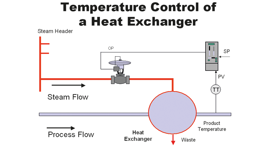
Figure 3 shows a heat exchanger being controlled by a single temperature controller. The temperature of the process fluid is the input to the controller, and the controller’s output is fed directly to the steam valve. This method of control is not an ideal method of controlling any slow process, and in particular in the case of a heat exchanger it is particularly bad. There are two reasons for this. Firstly, any slow process like this exchanger can only be tuned very slowly, because when tuning self-regulating processes one generally sets the integral term in the controller close to the dominant time constant of the process. This often means integral times of many minutes per repeat.
With slow settings like this, the controller can only make slow corrections if any load disturbances arise. In the case of the heat exchanger under discussion, the steam is fed from a header that has other take-offs leading from it. This can result in fluctuations of pressure in the header. If, for example, the header steam pressure suddenly dropped by 3% as steam was drawn off to another process, the steam flow to the exchanger would be reduced. The controlled temperature would then slowly start to drop. The controller with its slow integral would take a long time to catch and correct this, and large control variance would result. Secondly, any valve problems like hysteresis cause havoc in slow control loops with long integral settings, as can be seen in Figure 1, and as discussed in previous articles.
Now, what one must realise is that the output of a controller sets the position of the valve stem. If the valve was perfect without hysteresis, had linear installed characteristics, and there were constant pressure conditions in its feed line, then this would result in achieving the correct amount of flow
through the valve to satisfy the dictates of the controller. In reality, valves are seldom perfect and there is no guarantee that the stem will move to the position as dictated by the controller
If it were possible to ensure that the correct flow rate did follow the controller’s output, as would happen if we had a perfect valve, then the problems would be overcome. So how then can one make a real valve with its problems into a perfect valve?
The answer is very simple. One makes use of a technique called cascade control, whereby a second controller is used to control the flow of fluid through the valve.
Flow controllers are tuned with parameters that are lightning fast compared with those in the temperature controller. The time constant of a flow loop is in the order of one or two seconds, which is what the integral is set to in the flow controller. This means that the flow controller is capable of correcting for problems like line pressure variations, non-linearity and hysteresis in the valve relatively quickly, so the temperature process will not be affected. Even if the flow loop suffers from something like stick-slip cycling, and relatively bad hysteresis, the average flow through the valve will probably be more than good enough to keep the temperature on setpoint.
Terminology used can differ widely. As mentioned in previous articles there are no standards in control. The temperature loop can be called the primary, master or outer loop, and the flow loop the secondary, slave, or inner loop, respectively.
Cascade control can really work brilliantly, even as mentioned above, with relatively poor valves. As discussed, it effectively takes the valve problems out of the equation, including variations in pressure in the valve line, and in fact could be said to have made a bad valve into a good one.
In general, I believe that cascade control is almost mandatory for any critical slow control process in a plant. I have often persuaded plants to install cascade systems on important slow loops with absolutely excellent results, and resulting in vastly improved control performance and variance.
Cascade systems are typically found with the following combinations:

Sometimes people become very confused about the purpose of cascade control, and I have often heard process operators expressing the opinion that it is stupid having two controllers to control only one valve. Confusion also often reigns when it comes to level control with a cascaded flow control on the valve. Many plant personnel believe the level controller is there to keep the level constant, and the flow controller is there to keep the flow constant. Unfortunately, the second law of control states that you can only control as many variables as you have valves, so it doesn’t work that way. I often have quite a job explaining that the only reason for flow control is to ensure that the valve does its job correctly.
In passing, I would mention that this combination is particularly effective, as level is an integrating process, which is very likely to cycle continuously with any hysteresis in the valve. Control will also be adversely affected with any non-linearity in the valve. Adding the flow loop now takes the valve out of an integrating loop and puts it into a self-regulating loop, which is faster and subject to far fewer problems.
One very important point to remember is that cascade control can only work really well if the secondary process is ideally ten times faster than the primary process. Why? The reason is that cascade loops are interactive. If they both have similar response times they will tend to fight each other and could be very cyclic. A general rule of thumb is that if the secondary is less than about six times faster than the primary, then it may be better to dispense with the cascade entirely.
This article was written in the evenings during a course recently presented at a petrochemical plant in Saudi Arabia. A delegate asked me what I meant by the ‘speed’ of a process, and if this term also includes the controller tuning. The speed of a process is best judged by the ultimate frequency of that process. (Note: The ultimate frequency is the frequency at which the loop oscillates with sufficient gain inserted in a proportional-only controller). Another, and rougher, method of judging speed is by looking at the response time of the process to a step change on the input.
In conclusion, I would urge people to try using cascade control on slow and important loops where performance is not as good as desired. If it is set up properly the results will be very rewarding.
About Michael Brown

Michael Brown is a specialist in control loop optimisation, with many years of experience in process control instrumentation. His main activities are consulting and teaching practical control loop analysis and optimisation. He now presents courses and performs optimisation over the internet.
His work has taken him to plants all over South Africa and also to other countries. He can be contacted at: Michael Brown Control Engineering CC,
| Email: | [email protected] |
| www: | www.controlloop.co.za |
| Articles: | More information and articles about Michael Brown Control Engineering |


© Technews Publishing (Pty) Ltd | All Rights Reserved
 printer friendly version