With all the focus on IS loop approval, it is easy to forget to check that the loop will function correctly to see whether the field device has sufficient power
From a safety perspective this is extremely concerning, as most processes have high trip points. Do not rely on ATL/NB for operational functionality when an Ex certificate is issued.
IS compatibility
An IS Interface has maximum output parameters for voltage (Uo), current (Io) and power (Po). These are maximum output values under fault conditions, and are known as safety descriptions or entity parameters. The field device has maximum input parameters Ui, Ii and Pi, which are the maximum values that can be applied under fault conditions and still be safe.
For a safe loop, all three input parameters must be greater than or equal to output parameters
To complete the system loop approval, the electrical stored energy (cabling) needs to be considered. This will be covered later in the article.
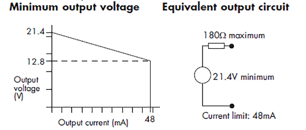
An IS interface has operational parameters. The Zener barrier is depicted below.
 MTL5521 SOLENOID/ALARM DRIVER.
Note: barrier/isolator safety parameters should not be confused with operational parameters.
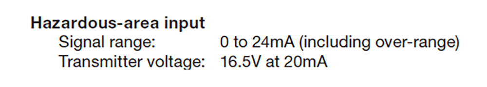
A field device has minimum voltage for functionality, and the current requirement will depend on device type
• To achieve IS compatibility with longer cables requires a higher Co value. To achieve a higher Co value, you need to reduce the Uo value. Reducing the Uo value invariably reduces the operating voltage.
• Using a lower working voltage with longer cables results in a lower voltage available to power the field device. This increases the risk that the field device will not function correctly.
Note that for any instrumentation loop, you need to ensure that field devices function 100%. This is in addition to the IS loop compatibility. To check the operating voltage at the end of the cable you need to look at the supply voltage from the IS interface at the highest loop current. The voltage drop across the current limiting resistor and drop over the full length (impedance) of the cable need to be taken into account.
Consider a typical
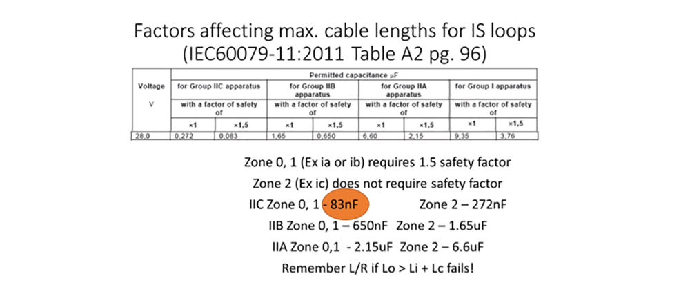
Table A.2 in IEC/SANS 60079-11 lists the maximum capacitance Co against output voltage of the IS interface. IEC/SANS 60079-11 also states maximum inductance, Lo. In the example below the maximum electrical stored energy that can be connected to the hazardous area terminals is
The output working voltage is
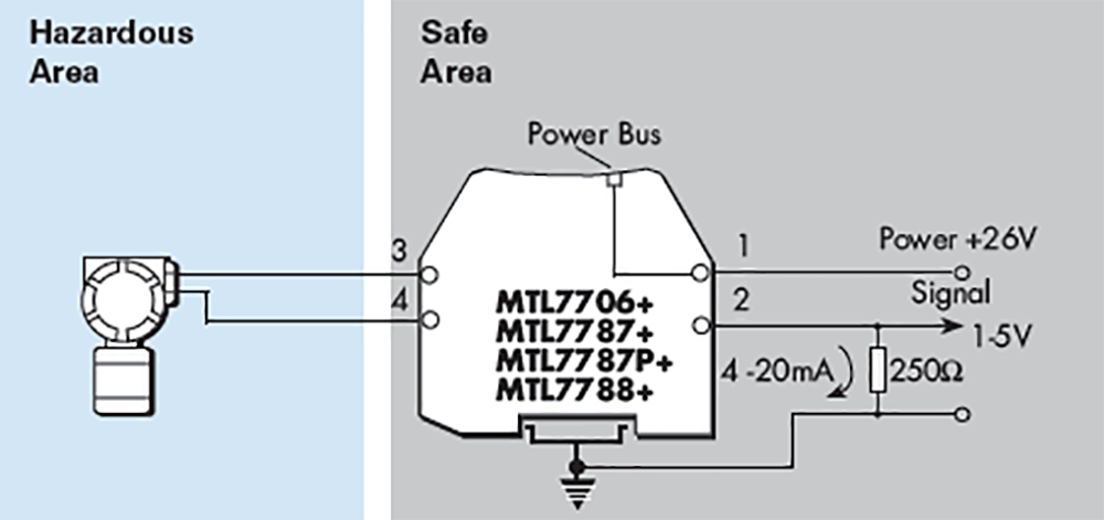
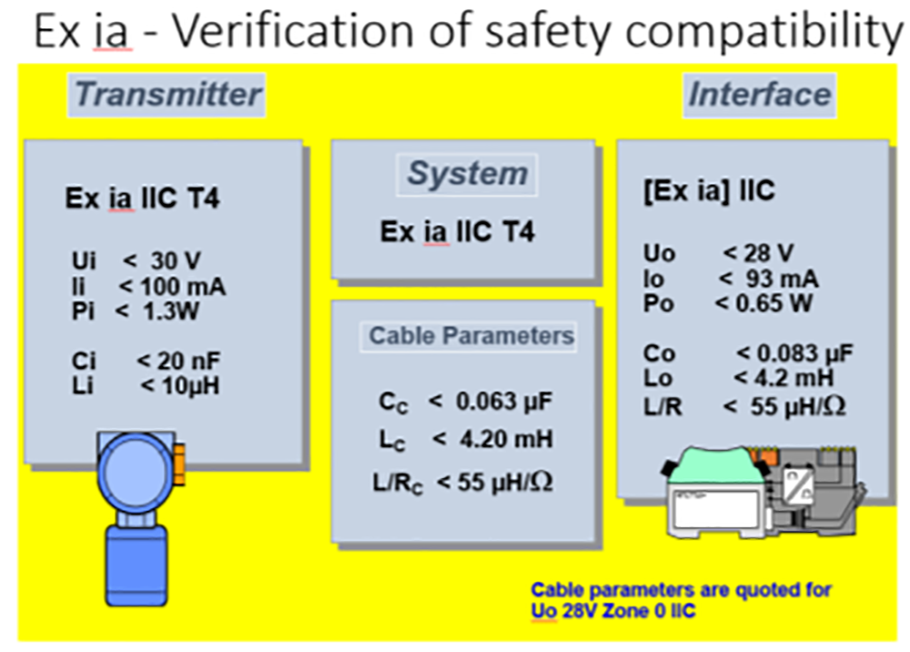 Figure 4: Instrument located in Zone 0 (or 1).
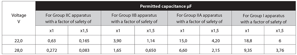 Figure 5: Permitted capacitance.
If longer cable runs are required, there are three options:
• Use an IS Interface with lower Uo value, which will allow a higher Co value.
• If the field device is in zone 2, then use Exic.
• If the gas group is IIB or IIA, then the loop can be certified as such, instead of IIC.
More information
• The MTL4541T was designed for longer cable runs with a Uo 22V Io 167mA. The lower Uo allowed for a higher Co 165nF for IIC zone 0/1, effectively doubling the cable length. Note that lower Uo translates into higher Io, which affects IS compatibility. The important issue here though is that the working voltage drops to 14 V at 20 mA. A voltage that is 2,5 V lower, and with longer cable (higher impedance), means lower voltage for the field device.
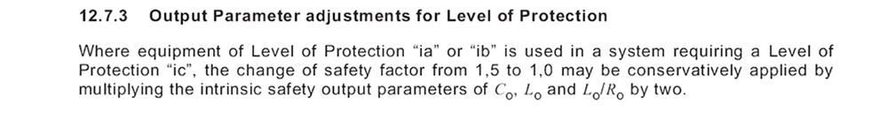
• Exic is a technique used for zone 2 (intrinsic safety in normal operation) where the 1,5 safety factor is not required, as shown in Table A.2 of IEC /SANS60079-11). This applies to cable parameters allowing for longer cable runs. For a standard 24 V loop (Uo = 28V) this changes the Co from 83 nF to 270 nF, allowing a significantly longer cable. The Co value is defined in IEC/SANS60079-11: 2011, Table A.2, (See Figure 6: Permitted capacitance.)
So any barrier/isolator with 28 V safety description will have Co = 83nF (Zone 0/1; IIC). In practice, this parameter will define the maximum allowable cable length.
Figure 4 shows an Exia loop with a Co=83nF. The maximum cable capacitance is Cc=63nF. With a typical cable capacitance of 95 nF/km, this would equate to maximum cable of 660 m.
If the loop were Exic, the Co=272nF, so Cc=252nF would theoretically allow 2,5 km of cable, so cable capacitance should not be a limiting factor. The limiting factor in this system is likely to be operating voltage at the end of the cable being high enough for the transmitter to work. In Figure 6, you can see that the system is Exic certified.
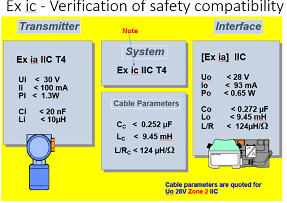 Figure 6: Field instrument in Zone 2.
For new installations requiring long cable runs, classifying the area as zone 2
Exic offers some flexibility, particularly for upgrades of old control systems, improving safety. Now let’s consider the impact of gas group on cable lengths for IS loops. If it is not possible to use Exic
Remember Figure 4. Ex ia loop with a Co=83nF; Cc=63nF; typical cable capacitance of 95nF/km = maximum cable of 660 m. If the loop was Ex ic, the Co=272nF, so Cc=252nF would theoretically allow 2,5 km of cable. i.e., no longer a limiting factor.
If the gas group were IIB, Co=650nF, which also eliminates capacitance as a limiting factor.
SANS/IEC60079-25 makes the statement below. In my opinion, using either makes very little difference, as the cable length will be limited by working voltage, not by cable capacitance.
Conclusion
A non-functional, but compatible, IS loop could potentially be more dangerous. Always check the operation beyond the full process range
For installations requiring long cable runs, classifying the area as zone 2, if possible, offers significant benefit. Alternatively, if there is an option for IIB
| Tel: | +27 10 055 7300/1 |
| Email: | [email protected] |
| www: | www.extech.co.za |
| Articles: | More information and articles about Extech Safety Systems |


© Technews Publishing (Pty) Ltd | All Rights Reserved
 printer friendly version