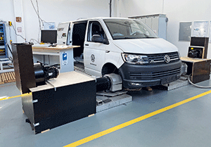

For small-series producers and manufacturers with a wide range of vehicle variants, being able to count on comprehensive test bench technology that is fast, flexible and cost-effective is hugely important. Kempten University of Applied Sciences (HS Kempten) has implemented a test bench just like this for ABT e-Line, allowing it to perform tasks such as testing Volkswagen vans that have been converted to an electric drive. PC-based control technology from Beckhoff serves as the central feature of the standard industrial components used.
The test bench at HS Kempten is primarily used for testing vehicle functions. It was developed in the Laboratory for Control Engineering and Vehicle Systems at HS Kempten, which examines applied research and development topics from the automotive and automation sectors. The lab was originally founded in 2016 for the purpose of testing components, although its range of activities has since expanded to include complex complete system test benches and even teaching, in addition to research.
The aims of the test bench are to test new vehicles and new functions as quickly as possible, and also to examine how individual functions influence each other. Another advantage is that vehicles can be tested in their original roadworthy condition rather than having to be modified, as is the case for most conventional test benches.

Florian Zerbes, a research assistant at the Allgäu Research Centre at HS Kempten, illustrates the scope and process of a test like this: “In the case of an electric vehicle, the aim is to test whether the HVAC systems, which draw their necessary power from the high-voltage battery, have an influence on the vehicle’s most important functions, such as switching on, switching off and driving. This involves specifying a test cycle that repeatedly starts, stops and accelerates the vehicle. The state of the vehicle changes as a result, i.e. the HVAC system is switched on or off and the battery charge level is varied. With the test bench at HS Kempten, this test can run completely independently over several hours or even days. The process involves continuously recording the data from the test bench and the vehicle so that it can be analysed and transferred into the final test result.”
Structure of the test bench
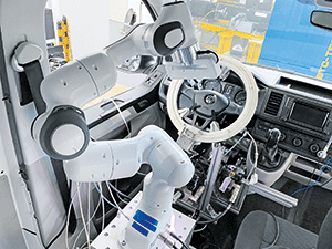
The output motors flanged to the vehicle wheels provide resistance to the propulsion of the wheels, which is intended to simulate driving on a road. A robot inside the vehicle turns the ignition key, moves the gearshift, and operates various buttons, such as those for interior climate control. Linear motors on the pedals press the accelerator and brake pedals, while a steering motor turns the steering wheel. A second robot outside the vehicle plugs and unplugs the various charging cables into and out of the charging socket.
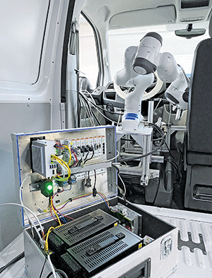
Measurement technology is used to acquire the currents and voltages in the vehicle’s wiring harnesses for subsequent analysis. The Beckhoff control platform – a C6030 ultra-compact Industrial PC with TwinCAT – communicates with the individual components and the vehicle via the CAN bus. This central control unit coordinates the individual components and controls them accordingly. A range of different tests can be implemented, all with different procedures. The seamless integration of the CAN devices in the EtherCAT control system is ensured by nine EL6751 EtherCAT Terminals and one-channel communication interfaces that integrate any CAN and CANopen devices.
During the test procedure, the vehicle faces driving conditions that it would on a real road. For this purpose, a drive test bench moves the wheels according to the simulated torques and can even accommodate steering movements. The simulation is so close to reality that the vehicle does not even ‘realise’ that it is on a test bench. Even the driver’s actions are simulated by corresponding actuators. Industrial robots perform most of the actions to facilitate as many different actions as possible. The surroundings are also simulated along with how the vehicle communicates with the environment – for example,via GPS. In addition to developing the real test bench, HS Kempten has also created a digital twin of the system. Not only does this facilitate pre-commissioning of the test bench, but it also offers comprehensive visualisation and monitoring of the system.
Industrial technology reduces costs and increases flexibility
A major consideration when developing the new test bench was how to make the system as cost-effective as possible. This was notably achieved by using standard industrial components such as converters, motors and controls. Another consideration was to ensure that the system was capable of being installed in and removed from the vehicle quickly, regardless of the vehicle model in question. The test bench therefore had to be easy to adapt.
With this in mind, Dr Andreas Stiegelmeyr, professor of Mechanical Engineering at HS Kempten, describes the requirements and implementation of the system as follows: “We developed a test bench that is capable of testing most vehicle functions using standard vehicle interfaces. This makes it possible to test functions with a high degree of connectivity with minimal effort, regardless of the vehicle type. What we have created is therefore a great alternative for vehicle manufacturers with a wide range of vehicle variants and for manufacturers of small series in particular.”
Zerbes adds: “We chose a system from Beckhoff as the central control because it already offers many different interfaces to industrial components. What’s more, the control technology can be easily expanded by adding EtherCAT terminals, and they are optimally distributed throughout a space due to the exceptional freedom of the EtherCAT topology. The sheer volume of hardware and software products available means that many measurement and control tasks can be completed with minimal effort. And to top it all off, PC-based control from Beckhoff offers a clear cost advantage over systems from the automotive sector.”

Toolchain to determine test sequences
The test sequences are written in Structured Text (ST) using a specially developed toolchain and generated with MATLAB/Simulink. This makes it possible to use TwinCAT and Simulink together effectively. Zerbes describes the details as follows: “Blocks that already contain the information for the hardware links can be generated automatically in Simulink. When compiling the respective model, the corresponding hardware links are automatically set by the TwinCAT Automation Interface and a link layer is created between the model and the hardware.”
The new toolchain offers the following capabilities:
• The required Simulink model can be created with virtually no effort.
• Different databases can be used without any problems.
• The connection to the hardware can be automated and configured directly in the Simulink model.
• Users benefit from an incredibly straightforward interface.
The current focus of the toolchain is on the CAN bus, which in concrete terms means that CAN message blocks can be created very quickly via a DBC file, for example. Blocks like this can then be directly connected to the rest of the model and the connection to the hardware can be configured in Simulink. Users can configure the individual messages via a GUI and configure other connections to the hardware directly in Simulink. Once the Simulink model has been created, it can be easily connected to TwinCAT via the toolchain with minimal effort. All users have to do is decide which Simulink model is to be linked to which TwinCAT project. Otherwise, everything runs completely automatically. At the same time, it is also possible to make adjustments to the TwinCAT project in terms of the hardware or the implementation of PLC projects.
© Technews Publishing (Pty) Ltd | All Rights Reserved