A controller responds to input changes with responses dependent on the way the P, I and D modules are configured. It is sometimes necessary to perform tests on a controller to ensure it does in fact respond correctly to changes on its input. This is particularly true for controllers in many digital systems and even more so in the case of many PLCs, where controllers often do not actually respond correctly to input changes. (This may be due to a fault in the controller’s software, but often, it is because the user has set up the controller incorrectly).
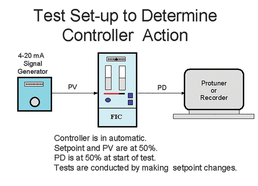
A test setup is shown in Figure 1. To perform the tests, the controller needs to be disconnected from the loop. The input (PV) 4-20 mA signal is fed into the controller from a signal generator. The controller is on local setpoint and the output (PD) 4-20 mA signal is fed into a recorder, or the Protuner if you have one.
Each test is performed with the controller in automatic. Before starting a test, the controller is switched to manual. The signal generator and the controller’s outputs are set to 50% (12 mA). The setpoint is also set to 50%. When the controller is switched to automatic the output should remain running at a constant 50%. The tests can then be started. These will be discussed later in this series as each type of control action is discussed.
Controller PID algorithms
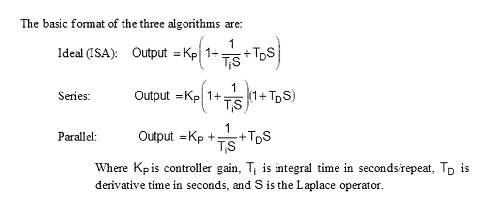
A controller is essentially a mathematical calculating unit. It is important to know which algorithm (equation) it uses in performing its function. Although control academics are always presenting specialised algorithms to help deal with the control of difficult or specific processes, commercial controllers generally employ one of three algorithms. Some manufacturers allow you to choose between two, or even between all three of these.
All three algorithms essentially perform PID control more or less equally well. However, what is not generally known is that different tuning would have to be set in each of them if one was to use P, I and D parameters to control a particular process and also achieve the identical response from each controller.
Although the names I have used for these algorithms are in common usage, there are, as always, no standards and many of the manufacturers use other and often confusing nomenclature. The names given here will be used throughout this series to identify a particular algorithm.
Historically it is not quite clear how and by whom the algorithms were developed, but I suspect that the Ideal was the first, as it appeared many years ago in the Transactions of the ISA. Possibly it was formulated by the famous Nichols. Several articles I have read claim that the Ideal algorithm was not in fact suitable for use to manufacture the pneumatic controllers of that era, which they needed to build in modular form. This was because a full three-term pneumatic PID controller was very expensive and it was far more cost-effective for users to order controllers with only the control terms that were required for their applications. If, at a later date, they did require an additional term, then they could order a kit of parts that could easily be added into the controller. It was easier to make such a modular controller by slightly modifying the algorithm. This was the Series algorithm.
The Series algorithm effectively became the standard at that time and except for a few controller manufacturers, all controllers were made like this. When electronic analog controllers were developed in the 1960s the same algorithm was retained.
Digital controllers
Digital controllers appeared in the 1980s. The old established instrumentation companies were entering the era of the DCS, and PLC manufacturers, who up to that time were only interested in digital on/off control, started expanding their products to include analog control capabilities.
The latter had little to no experience of feedback control and their programmers probably acquired their knowledge from reading textbooks on PID. They found the Series and the Ideal algorithms and, not fully understanding why the mathematicians of old had bothered to multiply the I and D terms by the P gain, they also came up with the Parallel algorithm. This was termed the Independent algorithm by one of the large PLC manufacturers which proclaimed it as superior because the I and D terms were not affected by changing the P term. Although this sounds intelligent, it shows that the people who invented that algorithm had little practical knowledge of control. The reasons for this opinion of mine will be explained more fully in later articles in this controller series.
Initially, many PLC manufacturers used only the Parallel algorithm in their products, but except for one, the prominent DCS manufacturers stuck to the Ideal or Series algorithms. However, in recent years some of them started offering it as their default algorithm, or as an alternative. Again, in my view, people who program controllers and who offer the Parallel algorithm as a default display that they have little understanding of the practical aspects of control.
It is significant to note that although many of the digital controller manufacturers originally employed the Parallel algorithm, all of them, as far as I am aware, now offer a choice of at least one of the others, mainly because of unfavourable user reaction to the Parallel algorithm.
Tuning
The main problem is in the tuning. The Parallel algorithm is generally much harder to tune by trial and error than Series or Ideal.
To understand this, one must realise that about 98% of loops worldwide are tuned by trial and error, or if you prefer, playing with the knobs. In general, very few people are really capable of achieving good tuning this way, but there are some who have, over the years, developed a wonderful touch for trial-and-error tuning and have become extremely proficient in this art. This experience has generally been gained on controllers that are equipped with Series or Ideal algorithms and the tuning for both of these is identical for P + I tuning. It only differs for P + I + D tuning. (An inspection of the equations above will explain why this is so, because when D is set to zero the equations become identical).
If you were to take one of these highly experienced tuning wizards and ask him (or her) to tune a loop that had a controller with a Parallel algorithm, the result would be catastrophic because the ‘feel’ that the person had developed using the Series or Ideal algorithm is of no use whatsoever when tuning a Parallel controller, which works completely differently. For example, if you had a loop that contained a Series or Ideal controller and the loop was cycling badly in automatic, you would generally reduce the proportional gain to try and stop the cycle. However, if you were to do this on a loop controlled by a Parallel controller, the loop would cycle more.
Reasons for the strange behaviour of the Parallel algorithm, and why it is so difficult to use, will be given when the I term is described later in this controller series and also when tuning is covered, which will be much later in the Loop Signature series.
About Michael Brown

Michael Brown is a specialist in control loop optimisation with many years of experience in process control instrumentation. His main activities are consulting, and teaching practical control loop analysis and optimisation. He gives training courses which can be held in clients’ plants, where students can have the added benefit of practising on live loops. His work takes him to plants all over South Africa and also to other countries. He can be contacted at Michael Brown Control Engineering cc,
| Email: | [email protected] |
| www: | www.controlloop.co.za |
| Articles: | More information and articles about Michael Brown Control Engineering |


© Technews Publishing (Pty) Ltd | All Rights Reserved
 printer friendly version