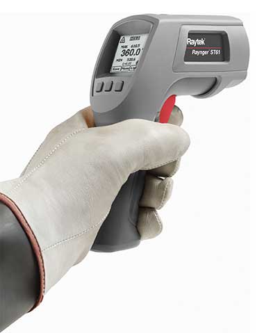

Since electrical currents generate heat, checking temperature is an effective method of condition monitoring in electrical systems. Non-contact, infrared thermometers enable such checks to be carried out quickly, efficiently and safely, without the risk of electric shocks or the need to shut down the plant or facility. Typical areas of use include electrical connections, electric motors, transformers, wires and cables, uninterruptible power supplies, backup batteries and light fittings.
Troubleshooting with infrared thermometers
To find a hot spot in electrical systems, aim the infrared thermometer outside the area of interest. Squeeze the trigger and hold it down as you scan across the target with a slow up-and-down, side-to-side motion. Laser sighting shows you the exact area of measurement. Temperature variations appear instantly in the LCD readout. Once you have found the hot spot, you can zero in on the component causing the problem.
Finding faulty components
As the condition of an electrical component deteriorates, its resistance can increase and generate more heat. As the component temperature rises, the resistance increases further, generating even more heat. By utilising infrared thermography to inspect electrical systems and components under full load, the faulty components can be identified and classified by severity.
Check for overloaded circuits
As the load increases in a circuit, the temperature of its components will increase proportionately. An even load on each phase of a three-phase system, for example, should result in uniform temperature on all three phases. An anomaly is identified when the overall component and conductor temperature is too high, indicating an overload condition. An unbalanced condition can also be a problem, and is identified by the conductors not displaying a balanced or equal temperature.
Monitoring localised resistance
Resistance in an electrical circuit comes from components such as connections, wires, fuses, switches and breakers. Under standard operating conditions, each component will have a certain ‘normal’ resistance associated with it. It is when the resistance deviates from this norm that the component begins to heat up and must be identified and repaired.
As the component continues to deteriorate, the temperature will continue to increase until complete failure occurs. This type of fault can be identified because there is a hottest point, i.e., the heat being generated is greatest at the fault point with a tapering-off as one moves outward.
Detecting harmonic disturbances
Harmonics are currents or voltages that are multiples of the basic incoming frequency serving an electrical distribution system. The most damaging are high-frequency harmonics as these can cause overheating and even melting of components. Other equipment affected by harmonics are transformers, standby generators, motors, telecommunications equipment, electrical panels, and circuit breakers.
Identifying poor connections
Poor connections are one of the most frequently found problems in electrical systems. Routine inspection with an infrared thermometer lets you find these problems. The majority of thermal electrical problems involve improper torque specifications or improper installation at the junction points. A loosely torqued connector effectively reduces the surface area in which current can flow and consequently increases the contact resistance. Oxidation built up at the connection point can compound the problem by causing an additional rise in resistance. Most conductor, insulation and component problems can be traced to a poor connection somewhere.
Regular inspection pays dividends
An inspection with an infrared thermometer should be performed regularly in manufacturing plants. All cable runs, bus ducts, distribution panels, motor control centres, etc., should be checked for hot spots or heat imbalances. This can identify loose connections, overloads, unbalanced loads, and high neutral currents that need to be corrected.
Infrared thermometers provide an easy way to detect small changes in temperature – simply point, shoot and read. It is a non-contact, non-destructive and simple method of detecting impending electrical problems. Inspections can be at any time without shutting down the plant or facility. Since all common electrical problems announce themselves as an increase in temperature, they are easily detected in a minimal amount of time. Precise pinpointing of problems minimises the time required for predictive maintenance, and enables you to repair only what requires repairing, reducing maintenance time and unscheduled shutdowns and avoiding replacing good components.
| Tel: | +27 11 608 1551 |
| Email: | [email protected] |
| www: | www.randci.co.za |
| Articles: | More information and articles about R&C Instrumentation |

© Technews Publishing (Pty) Ltd | All Rights Reserved