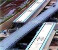

In Shanghai, the Transrapid magnetic levitation system is used for public transportation for the first time. The Transrapid does not have much in common with a rail vehicle. Switching the tracks required new technical solutions. The line consists of reinforced concrete supports connected with horizontally arranged reinforced concrete beams to create an endless bridge construction. Where a turn-off point is required the concrete is replaced by steel. A switch is formed by a 70 m long steel beam spanning five supports. The beam is bent to the desired direction of travel using SEW-Eurodrive gear motors.

In order to move a switch, a total of nine gearmotors controlled with Movidrive drive inverters are required. Five of them operate the mechanical locking mechanisms of the switches that are required due to strict safety measures. Four drives are directly involved in the position controlled setting process of the switch or the bending of the steel beam. A perfect bending line is always maintained independent of environmental conditions, such as extreme temperature or strong wind. This is important to keep the stress in the steel as low as possible which positively affects the overall life of the structure.
The complete control and drive electronics of the switch is doubled by a redundant design that guarantees high availability of the system. Two parallel PLCs operate in HOT standby mode. This means that if one PLC malfunctions, the system immediately switches over to the second one. Each of these PLCs is master on a Profibus line. All fieldbus-capable sensors and actuators are redundantly distributed to both Profibus lines.
The setting process of a switch from base to turnout position must be completed within 29 seconds. At the end, the steel beam must be bent to the outside by approximately 3,5 m. Since the setting time also includes the mechanical locking and unlocking of the complete structure, only 14 seconds remain for the actual setting - a very short time when considering the size of the structure.
Setting the switch requires an overall power of about 80 kW, which is distributed to four drives. At the end of the beam, where greatest deflection is experienced, two gearmotors engage with a joint gear rack. Each of these motors requires a power of about 30 kW during the setting process. The two gear units with a gear ratio of 1:76 each transfer 10 000 Nm to the gear rack.
The third gearmotor with a ratio of 1:272 is located in the middle of the switch as an auxiliary drive. It must ensure within the same time period that the switch is deflected by only one-third of the travel at the end. Without it, it would be impossible to achieve an optimum bend in the steel beam. The third motor is rated at 10 kW and transfers 10 000 Nm. The fourth drive operates at the beginning of the steel beam. At this point the switch travels only a very short distance, and it is here that the gearmotor supports the bending of the switch. This motor is rated at 10 kW.
The PLC sends the target positions via Profibus to the position-controlled Movidrive, which moves the switch to the required position with the support of its torque slave. The switch auxiliary drive in the middle must oppose the natural bending efforts of the steel. Without it, the switch would form a bending line that would cause excessive stress in the steel. The drives must maintain a fixed path ratio to each other. This is achieved by the digital position control of Movidrive units in the drives. The fourth switch setting drive, or push-rod drive, operates like all other locking drives without speed feedback and positions with limit switches.
| Tel: | +27 11 248 7000 |
| Email: | [email protected] |
| www: | www.sew-eurodrive.co.za |
| Articles: | More information and articles about SEW-EURODRIVE |
© Technews Publishing (Pty) Ltd | All Rights Reserved