

PUFT theory and objective
The primary objective of the PUFT implementation is to improve and optimise operation and machine efficiency on a coupled manufacturing line by making the best use of current assets.
PUFT theory utilises a system’s constraints, over-capacity and acceleration capability, to predict the location and magnitude of free time at workstations. PUFT has evolved from production theories like JIT and Kanban as these are not applicable in a high-speed coupled manufacturing installation with fixed accumulation. Free time is available due to this accumulation and stoppages on the production line.
Coupled manufacturing refers to an installation where machines are connected to each other by conveyors or storage bins. A machine processes product and feeds it into an accumulator from where the next machine on the line fetches, processes and feeds its accumulator. This continues until the product exits the last machine into the warehouse.
PUFT is applicable to any coupled manufacturing production line whether it consists of high-speed machines or the manual assembly of products.
Free time defined
Free time, in the PUFT context, is defined as the time available for a production machine operator to stop his machine without affecting the overall performance of the production line.
Importance of the V-Profile
High-speed production lines are designed such that machine throughput-rates are lowest in the centre and highest at the start and end. This is the V-profile.
The machine at the bottom of the V needs to be kept supplied with product. In a food or beverage line this is where product and empty containers meet. If it stops, production stops. The longer it runs, the more product enters the warehouse. PUFT monitors if the V moves from its designed position and can operate with a dynamic V-profile.
Dynamic free time
Upstream of the V, a machine that keeps its accumulator filled is able to create free time by virtue of the fact that its downstream machine has product to draw on and therefore stay running. Downstream of the V, machines draw product away from the V-machine to ensure it has accumulator space for its product. These create dynamic free time.
Becoming the constraint
Any machine that does not fill or drain the V-machine will become the current bottleneck (CBM) or current constraint machine (CCM). We define the CBM as the machine with the lowest free time on the production line. This is a good indicator that the machine is not performing well. A machine transitions from CBM to CCM when it stops producing. When there is a CCM there is a direct cost to production line efficiency.
The PUFT real-time advantage
Where PUFT has an advantage over traditional methods is that it allows the state of the production line to be monitored, analysed and displayed in real-time at each machine. Existing technology adopts a post-mortem approach. Stoppages are analysed after the fact.
This allows the operator to make decisions based on the current state of the production line. The operator is aware that if his machine is the CBM, stopping it will make it the CCM and impact on line efficiency. Maintenance or cleaning decisions are made based on available free time. These all combine to improve overall line efficiency.
Static free time
When a machine stops due to operator intervention, emergency stop or breakdown, PUFT prompts the operator for the expected downtime. This is static (breakdown) free time. Free time at any machine is the sum of its dynamic and static free times.
When static downtime is entered, it is propagated to all other machines on the production line. Since the breakdown machine is expected to be stopped for the given time, all machines benefit. PUFT monitors MTBF and MTTR and can use this to broadcast estimated downtime without operator intervention.
Free time is an advanced warning
PUFT predicts free time in four different line states: Sleep, Start-Up, Running and Run-Out. Many production lines do not have line-of-sight communication between machines. When the line has emptied of product for example, ie, Run-Out and gone to a Sleep state, each operator has an indicator showing when product is expected to arrive when it restarts. Depending on the line configuration, this could be an hour or more from the first machine starting to run, to product arriving at the last. Operators can use this time more effectively than if they had inaccurate or no knowledge of the state of the production line.
PUFT equipment and installation
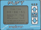
PUFT equipment at each point-of-interest consists of a Heartbeat device which gathers all sensor signals and a Predictor which displays free time to the operator. The line manager has the option of a Globe device which gathers data from the Predictors and displays a summary of the current state of the line. The Globe has an Ethernet connection and serves up Web-pages to any desktop PC browser.
Installation of the PUFT system is simple and non-invasive. Each point requires power and sensors to count product entering and leaving the machine. Communication between Predictors uses proprietary wireless adapted for industrial environments.
Additional features
Predefined messages may be broadcast to other Predictors and Globe and by SMS to pre-programmed phone-numbers. Data for each machine is stored continuously, eg, 121 days at 5 minute intervals and retrieved via USB. Line Configurations may be changed by uploading a parameter file generated from a spreadsheet allowing product changes with varying pack sizes to be set up quickly. Simulation Mode provides a sophisticated mechanism to model a line and experiment with changes before deployment into the field.
For more information contact Dale Whitfield, PUFT Group, +27 (0)21 788 5838, [email protected], www.puft.co.za


© Technews Publishing (Pty) Ltd | All Rights Reserved
 printer friendly version