Pressure measuring instruments used in sterile processes must be exceptionally tough, with special designs and materials required to combat the exposure to high temperatures and aggressive cleaning agents. Clean-in-Place (CIP) systems reduce the manual cleaning requirements and the idle down times within a sterile facility. Common CIP processes use acid or alkali based cleaning solutions at elevated temperatures (up to 80°C) and pressure of up to 410 kPa.
Compatibility with these aggressive environments is one of the challenges for sensitive pressure measuring instruments. An effective CIP process exposes the wetted materials of the sanitary pressure gauge to repeated cycles of wash, rinse and drain. The sterilisation-in-place (SIP) cycle is also carried out in this closed system. For a steam sterilisation process, the point within the piping system being exposed to the lowest temperature needs to be subjected to at least 120°C for over 20 minutes – and the trend is toward significantly higher temperatures. For instance, at this moment, some SIP cycles are running as high as 150°C.
Stainless steel, 316L, is compatible with most process media, but could have a limited life when exposed to the aggressive cleaning solvents. Sanitary process technology mainly uses corrosion resistant austenitic stainless steels as standard materials. 316L is commonly specified in the American markets, within Europe 1.4404 and 1.4435 are both used. If these are not process or cleaning compatible, numerous other materials are available to extend the expected life cycle of the pressure measuring instrument (eg, Hastelloy C276, titanium, Inconel and others).
Sanitary pressure measurement
Components of the measuring instrument must meet high demands, ie, resistance to high temperatures, aggressive detergents and increased pressure, at the same time they must maintain long-term measuring accuracy. A diaphragm seal pressure measuring assembly is often used to satisfy these requirements. To understand where the critical points are within a diaphragm seal system, it is necessary to give a short explanation of the functionality of a diaphragm seal installed on a pressure gauge.
A diaphragm seal assembly consists of a pressure gauge mounted to a diaphragm seal (a thin flexible diaphragm welded to a solid body) and a transmission fluid (system fill fluid). When using a diaphragm seal, the measuring instrument is separated from the process medium by the metal diaphragm (typical thickness of 0,05–0,1 mm) to prevent the process medium from coming in contact with the pressure gauge. The applied process pressure deflects the diaphragm and the displaced volume of fluid hydraulically transfers the pressure to the gauge. This methodology ensures accurate, reliable and repeatable pressure measurement.
An important element of the diaphragm seal system is the selection of the system fill fluid. When specifying the system fill fluid for a sanitary application, it is important to specify a type that holds FDA (American Food and Drug Administration) or USP (US Pharmacopoeia) approval. The system fill fluid needs to be compatible with the process medium for the rare situation when a breach occurs in the diaphragm and this fluid comes into contact with the process.
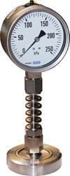
When converting a threaded pressure gauge to mate with a sanitary type of process connection, the use of a diaphragm seal is the most common approach. The pressure measuring gauge can be installed directly to the diaphragm seal, or via the use of a flexible capillary. For direct mounts containing high medium temperatures, a cooling element can be used between the gauge and diaphragm seal to dissipate the heat in order to protect the gauge. Gauge and seal combinations can be configured for easy pressure readings for horizontal and vertical piping systems. (Figure 1.)

Installation without obstructions
The sanitary diaphragm seal containing a flush diaphragm is installed into the process piping system by use of a process ‘T’, which has some disadvantages: dead-space, non-laminar flow and additional clamped connections. This can result in hard to reach areas for cleaning, crevices, pockets, reduced shear stress due to lower turbulence and additional potential leak paths.
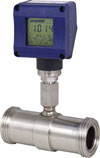
An inline diaphragm seal is perfectly suitable for use with flow applications with a low to medium viscous process medium. This diaphragm seal consists of a body with an internal cylindrical thin diaphragm. This sanitary assembly design does not require any instrument ‘T’ for installation into the process flow. The seal becomes an integral part of the piping system. Since it is entirely integrated, no turbulence, corners, dead spaces or other obstacles occur within the process flow. The medium flows undisrupted through this non-intrusive pressure measuring assembly providing the bases for self-cleaning and draining. (Figure 2.)

educe the intrusive tapping
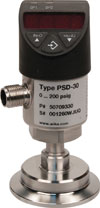
A standard sanitary pressure measuring instrument can be combined with other instruments into one device (transmitter, transducer, switch, temperature etc,) to minimise the number of installation taps required within the process piping system. Minimising the number of tapping locations and components in a sanitary system expedites cleaning by reducing the number of joints and potential crevices. Combining several instruments into one device also reduces the number of potential contamination points and leak points. All of which are desired goals for sterile manufacturing. (Figure 3.)

Dry measuring cell
Up to now only pressure gauges with diaphragm seals were available for the applications within the sanitary market. The new dry measuring cell (no system fill fluid behind the diaphragm) consists of an integral flush welded diaphragm element which uses its linear displacement (not the typical volume displacement) to sense and measure the pressure. This dry measuring cell technology has been used in other industries for numerous years and is now being applied in the demanding sanitary market.
One major advantage of this technology is the elimination of contamination risks to the process medium due to potential leakage of the system fill fluid from a damaged diaphragm seal. Another is the minimisation of the inherited false zero pressure shift due to the expansion or contraction of the system fill fluid resulting from exposure to temperature deviations. The dry cell technology removes the false zero due to the absence of any system fill fluid.
Conclusion
There are a wide variety of existing options to reduce the hygienic risk in pharmaceutical, biopharmaceutical, food, beverage and cosmetic plants, to ensure safe and clean pressure measurement. The inline instrumentation ensures no dead space and allows self draining. To assist in cleaning, combine several instruments into one device to minimise the number of tapping locations in the piping system. To avoid contamination by the system fill fluid in case of a possible diaphragm rupture, there is a dry measuring cell available.
Irrespective of the hygienic requirements, the correct application of available technologies can ensure accurate and reliable pressure measurement even under these tough process conditions.
| Tel: | +27 11 621 0000 |
| Email: | [email protected] |
| www: | www.wika.co.za |
| Articles: | More information and articles about WIKA Instruments |

© Technews Publishing (Pty) Ltd | All Rights Reserved