

In Part 1 of this two-part series on loop power isolators four applications were looked at in the November issue. In this issue the final six applications in this series will be covered.
Application 5: Using the LPI's internal clamp with a two-wire transmitter to protect the loop against open circuit
There are cases, when using 4-20 mA inputs to your PLC, RTU or DCS, where it is important that the current loop is not disrupted when the analog input to your PLC or RTU or DCS is unplugged or disconnected.
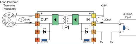
In these cases you can use the internal clamp of the LPI to protect the loop from open circuit if your PLC or RTU or DCS input is unplugged or disconnected. This is simply achieved by connecting the input clamp terminal 3 to your 0 V reference. If the analog input to your PLC or RTU or DCS is disconnected, the current will be diverted to 0 V through the clamp, saving the current loop from disconnection.
The voltage across the LPI will be clamped to 6,8 V in this condition - only slightly higher than the normal operating voltage of 1-5 V. This higher clamp voltage should be used when calculating maximum allowable loop resistance.
Note: The 'IN' side of the LPI is always connected to the side of the loop supplying the loop power, so in this application the two-wire transmitter is connected to the OUT terminals of the LPI.
Because of the 2 mm² wire size capability of the LPI terminals, the LPI can also act as the field interface terminals, saving you the extra termination and wiring cost.
To determine the maximum loop resistance of your cabling that you can tolerate in your loop with the clamp in operation, apply the following formula:
where:
RMAX is the maximum resistance in the loop without causing measurement error (in Ω).
VSmin is the minimum voltage of the power supply used to drive the loop (in V).
VTmin is the minimum voltage required by the two-wire transmitter for operation (in V).
For reliable operation over the long term, you should design for less initial cable resistance than this maximum value. This provides a safety factor to account for increase in resistance of terminations and wiring with age or weathering.
A sensible value to use for this safety factor would be 100 Ω (equal to 2 V at 20 mA).
Application 6: Using the LPI's internal clamp with a four-wire transmitter to protect the loop against open circuit
When using 4-20 mA inputs to your PLC, RTU or DCS, there are cases where it is important that the current loop is not disrupted when the analog input to your PLC or RTU or DCS is unplugged or disconnected.
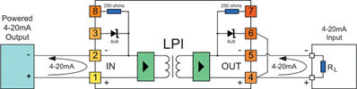
In these cases you can use the internal clamp of the LPI to protect the loop from open circuit if your PLC or RTU or DCS input is unplugged or disconnected.
In four-wire current transmitter applications this is simply achieved by connecting the output clamp terminal 6 to the current output terminal 4 of the LPI. If the analog input to your PLC or RTU or DCS is disconnected, the current will be diverted through the clamp, saving the current loop from disconnection.
The voltage across the LPI will be clamped to 6,8 V in this condition - slightly higher than the normal operating voltage of 1-5 V. This higher clamp voltage should be used when calculating maximum allowable loop resistance.
Note: The 'IN' side of the LPI is always connected to the side of the loop supplying the loop power, so in this application the four-wire transmitter is connected to the IN terminals of the LPI.
Because of the 2 mm² wire size capability of the LPI terminals, the LPI can also act as the field interface terminals, saving you the extra termination and wiring cost.
To determine the maximum loop resistance of your cabling that you can tolerate in your loop with the clamp in operation, apply the following formula:
RMAX = RT - 500
where:
RMAX is the maximum resistance in the loop without causing measurement error (in Ω).
RT is the maximum load resistance that the current transmitter can drive (in Ω).
For reliable operation over the long term, you should design for less initial cable resistance than this maximum value. This provides a safety factor to account for increase in resistance of terminations and wiring with age or weathering.
A sensible value to use for this safety factor would be 100 Ω (equal to 2 V at 20 mA).
Application 7: Using the LPD to isolate multiple 4-20 mA outputs from a PLC or DCS
In this application, the LPD can be inserted directly into the 4-20 mA output loops between the transmitter and the load.
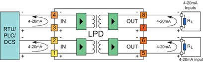
Each LPD circuit will consume less than 3 V from the loop. For loop resistance calculation purposes this is equivalent to inserting an additional resistance of 150 Ω into the current loop.
Note: The 'IN' side of the LPD is always connected to the side of the loop supplying the loop power, and so in this application, the transmitter outputs are connected to the IN side of the LPD.
Because of the 2 mm² wire size capability of the LPI terminals, the LPI can also act as the field interface terminals, saving you the extra termination and wiring cost.
To determine the maximum loop resistance of your cabling that you can tolerate in your loop, apply the following formula:
RMAX = RT - RL - 150
where:
RMAX is the maximum resistance in the loop without causing measurement error (in Ω).
RT is the maximum load resistance that the current transmitter can drive (in Ω).
RL is the total resistance of all loads in the loop (excluding the LPI) (in Ω).
For reliable operation over the long term, you should design for less initial cable resistance than this maximum value. This provides a safety factor to account for increase in resistance of terminations and wiring with age or weathering.
A sensible value to use for this safety factor would be 100 Ω (equal to 2 V at 20 mA).
Application 8: Using the LPD to isolate multiple 4-20 mA inputs to a PLC or RTU (with passive inputs)
In this application, the LPD can be inserted directly into the 4-20 mA input loops between the field-mounted two-wire transmitter and the PLC or RTU input.
Each LPD circuit will consume less than 3 V from the loop. For loop resistance calculation purposes this is equivalent to inserting an additional resistance of 150 Ω into the current loop.
Note: The 'IN' side of the LPD is always connected to the side of the loop supplying the loop power, and so in this application, the two-wire transmitters are connected to the OUT side of the LPD.
Because of the 2 mm² wire size capability of the LPD terminals, the LPD can also act as the field interface terminals, saving you the extra termination and wiring cost.
To determine the maximum loop resistance of your cabling that you can tolerate in your loop, apply the following formula:
where:
RMAX is the maximum resistance in the loop without causing measurement error (in Ω).
VSmin is the minimum voltage of the power supply used to drive the loop (in V).
VTmin is the minimum voltage required by the two-wire transmitter for operation (in V).
RL is the resistance of the PLC/RTU input (in Ω).
For reliable operation over the long term, you should design for less initial cable resistance than this maximum value. This provides a safety factor to account for increase in resistance of terminations and wiring with age or weathering.
A sensible value to use for this safety factor would be 100 Ω (equal to 2 V at 20 mA).
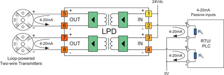
Application 9: Using the LPD to isolate multiple 4-20 mA inputs to a DCS with active (two-wire tx) inputs
In this application, the LPD can be inserted directly into the 4-20 mA input loops between the field mounted two-wire transmitter and the DCS input.
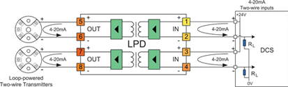
Each LPD circuit will consume less than 3 V from the loop. For loop resistance calculation purposes this is equivalent to inserting an additional resistance of 150 Ω into the current loop.
Note: The 'IN' side of the LPD is always connected to the side of the loop supplying the loop power, and so in this application, the two-wire transmitters are connected to the OUT side of the LPD.
Because of the 2 mm² wire size capability of the LPD terminals, the LPD can also act as the field interface terminals, saving you the extra termination and wiring cost.
To determine the maximum loop resistance of your cabling that you can tolerate in your loop, apply the following formula:
where:
RMAX is the maximum resistance in the loop without causing measurement error (in Ω).
VSmin is the minimum voltage of the power supply used to drive the loop (in V).
VTmin is the minimum voltage required by the two-wire transmitter for operation (in V).
RL is the resistance of the PLC/RTU input (in Ω).
For reliable operation over the long term, you should design for less initial cable resistance than this maximum value. This provides a safety factor to account for increase in resistance of terminations and wiring with age or weathering.
A sensible value to use for this safety factor would be 100 Ω (equal to 2 V at 20 mA).
Application 10: Dealing with zero loop resistance when using the LPI
The LPI is optimised to minimise the effective inserted loop impedance, but does require a minimum of 100 Ω of load impedance, (or 2 V) on the output to maintain operation.
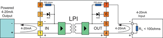
In some applications, when using four-wire transmitters, the load being driven is lower than this minimum value, and additional load needs to be inserted into the output loop to bring the minimum load up to the required 100 Ω.
One solution for this is to use the internal 250 Ω resistor to provide this additional resistance. When connected as shown in the diagram, the internal resistor is used in series with the current loop to provide an additional 250 Ω of loop resistance. This brings the LPI back into specification without the need for any additional resistors.
Note: The 'IN' side of the LPI is always connected to the side of the loop supplying the loop power, so in this application the four-wire transmitter is connected to the IN terminals of the LPI.
Because of the 2 mm wire size capability of the LPI terminals, the LPI can also act as the field interface terminals, saving you the extra termination and wiring cost.
To determine the maximum loop resistance of your cabling that you can tolerate in your loop with the clamp in operation, apply the following formula:
RMAX = RT - RL - 400
where:
RMAX is the maximum resistance in the loop without causing measurement error (in Ω).
RT is the maximum load resistance that the current transmitter can drive (in Ω).
RL is the resistance of the connected load (in Ω).
For reliable operation over the long term, you should design for less initial cable resistance than this maximum value. This provides a safety factor to account for increase in resistance of terminations and wiring with age or weathering.
A sensible value to use for this safety factor would be 100 Ω (equal to 2 V at 20 mA).
For more information contact Ian Loudon, OmnIflex, +27 (0) 31 207 7466.
About Omniflex
Omniflex has accumulated over 40 years of experience in signal conditioning system design and has produced many innovative products in this particular field.
| Tel: | +27 31 207 7466 |
| Email: | [email protected] |
| www: | www.omniflex.com |
| Articles: | More information and articles about Omniflex Remote Monitoring Specialists |


© Technews Publishing (Pty) Ltd | All Rights Reserved
 printer friendly version