Modern strain gauge production processes are based on thin-film technology. It unites all the advantages of the conventional strain foil gauge without possessing any of its disadvantages. The main advantages are very low temperature sensitivity and excellent long-term stability. In most cases the deformable body is a diaphragm whose simplest form is a circle.
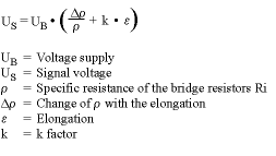
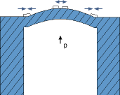
Four foil resistors are connected together to form a Wheatstone bridge. The resistors are positioned in those areas of the diaphragm where the greatest changes in stress occur. When pressure is applied, the resistors experience the greatest elongation at the centre of the diaphragm and the greatest compression in the edge zones. This results in the following equation:

Such strain resistor elements are made of diverse materials, eg NiCr and semiconductor materials such as silicon. The main differences lie in their k values.

The base materials for the diaphragms consist of metals that exhibit a low deformation hysteresis. CrNi steels are normally used in order to achieve a good degree of compatibility with the process media. Special materials such as Elgeloy or Hastelloy C4 are also used but only in specific applications because of the difficulties in their processing.
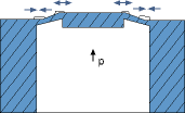
Regarding diaphragm shape, a distinction is drawn between circular and annular diaphragms. The advantage of an annular diaphragm is that there is no balloon effect (additional elongation) acting on all four resistors (which causes a linearity deviation). In the case of an annular diaphragm, the strain gauges are positioned over the inner and outer bending edge, as shown in Figure 1. This is where the diaphragm experiences the greatest changes of stress.

The production of thin-film pressure sensors is a combination of the high-precision mechanical fabrication of a deformable body and the covering of this body with strain gauges in a variety of processes. First, the thickness of the diaphragm must be finished to very close tolerances, mainly by lapping. The surface of the diaphragm is then prepared for the coating process by polishing to a maximum peak-to-valley height of approx 0,1 mm. At the next step, an insulating layer is applied to the polished stainless steel membrane. This step could be affected by making use of the PECVD process (plasma enhanced chemical vapour deposition), for example.

In this process a coat of SiO2 is applied to the diaphragm surface. SiO2 is comparable with glass in its insulating properties. The actual resistance layer is then applied in a sputtering process (cathode ray sputtering). This process is a controlled glow discharge and takes place in super-high-vacuum. The diaphragm material and the insulating layer enter into a molecular bond as the precondition for a break-free compound that guarantees very good long-term stability.
After the resistance layer has been applied in a thickness of 50 to 200 nm, the actual strain gauges are produced by means of photolithography in a wet etching process.
Further insulating, passivation and contacting layers are added, also making use of thin-film techniques. It is possible to include temperature compensation resistors in the sensor layout in addition to the strain gauges. Thin-film sensors are becoming increasingly important, particularly for high-pressure measurement.
Strain gauge transmission principles
Diverse types of strain gauge are used for electrical pressure measurement. Strain gauges themselves only convert a deformation (elongation or compression) into a change of resistance, so they must be applied to a deformable body. From the equation for pressure it is clear that a specific defined area A is required for the creation of a deformation in order to determine the force via pressure. Materials with very good elastic properties are used for these deformable bodies. Stainless steels are used as a rule because of their elastic properties and good compatibility with process media. Ceramic materials are also being used more and more often on account of their good diaphragm properties. It is a characteristic of these materials to produce a strictly linear elongation (in accordance with Hooke's law) on their surface when pressure is applied. This effect is used in the following conversion principles.

Diaphragm conversion
In most cases of diaphragm-based conversion, circular diaphragms or annular diaphragms are used. These diaphragms can be calculated and manufactured relatively easily.
The strain gauge is applied to the side facing away from the medium. One advantage of these diaphragms is that the measuring range is determined by the diaphragm diameter and/or the diaphragm thickness. When selecting the diameter and the thickness, it is usual to choose a diaphragm that achieves a maximum elongation of around 0,9 to 1 mm/m. This equals an elongation of around 0,1%. The pressure ranges in which these circular and annular diaphragms are used lie between around 100 kPa and approximately 400 MPa.
This information was extracted from The WIKA Handbook on temperature and pressure measurement.
| Tel: | +27 11 621 0000 |
| Email: | [email protected] |
| www: | www.wika.co.za |
| Articles: | More information and articles about WIKA Instruments |

© Technews Publishing (Pty) Ltd | All Rights Reserved