


In last month’s issue, the authors discussed how industrial control philosophy has gone almost full circle – it began with discrete, standalone controller units for each loop, then the mainframe computer approach looked set to permanently centralise all the control in plants. Then along came configurable (and very reliable) standalone controllers, which turned this around, the central controllers relinquished some of their work to these controllers out in the field. Further to this, instrument manufacturers began building more intelligence into their devices, giving the end user the option of freeing up some of the processing load of the controllers. Control buses evolved that allow for centralised control, distributed control and a mixture. While modern distributed control has the potential for offering higher ROIs, there is still reluctance in industry. This month’s article takes a look at what control in the field is all about – Ed.
Basics
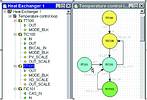
Control in the field is no more than the execution of control function blocks in field devices. A control loop is set up by linking together the inputs and outputs of the constituent function blocks, exactly as if the control was running in the controller. The only difference is that the control blocks themselves will be 'attached' to field devices. Depending on the host system configurator, it may be as simple as dragging and dropping the function block to a field device rather than a linking device or controller (see Figure 1).
As the control strategy is built up in the foreground, a list of all the links is compiled in the background. In addition to those between function blocks, links are also added to enable the parameters in each of the function blocks employed to be viewed by the host system. When the project is downloaded to the real network, every link is mapped onto a communication channel or so-called virtual communication relationship (VCR). A VCR is like a telephone line that allows two or more devices to talk to each other. In reality, three types of VCR are used by Foundation Fieldbus: publisher-subscriber, client-server and report distribution. Publisher-subscriber VCRs are used for links between blocks and are scheduled. Client-server VCRs are used for the unscheduled transfer of view data. Report distribution, also known as source-sink, is used to distribute trend and alarm information.
Communication on the fieldbus is controlled by the link active scheduler (LAS). This normally resides in the controller or linking device, but may also be located in a field device. The LAS directs the scheduled traffic by means of the so-called compel data (CD) schedule. This lists all the publishers with the exact instant and period they should be given permission to publish. The LAS synchronises control by working successively though the list, compelling each block to publish in turn. All devices requiring the published value (subscribers) are updated at the same instant in time. In the periods between scheduled traffic the LAS handles system requests for view data, write commands or broadcasts administrative data. The time taken to refresh the process data of the complete system is determined by the macro cycle, which comprises the CD schedule plus an additional fixed period for unscheduled traffic. It should be noted that depending on macro cycle length and amount of unscheduled traffic, it could take more than one macro cycle to update HMI data.
Optimising Macro cycle
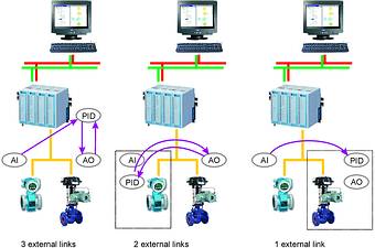
One way to optimise control is to reduce the macro cycle by cutting the scheduled traffic on the bus. This means reducing the links required to execute the control. Figure 2 shows an example of a PID control loop, where a flowmeter is used to control the valve positioner. There are three methods by which the control can be done:
1. When the PID loop is located in the controller, three external links are required:
* To send data from the transmitter AI block to the PID block.
* To send the result of the PID execution to the actuator AO block.
* To send the back calculation data from the actuator AO block to the PID block.
2. When the PID loop is located in the transmitter, two external links are required:
* To send the result of the PID execution to the actuator AO block.
* To send the back calculation data from the actuator AO block to the PID block.
3. When the PID block is located in the actuator, only one external link is required:
* To send data from the transmitter AI block to the PID block.
For a single loop, the savings are relatively small compared to the execution time of the blocks, especially when it is considered that loop execution is quicker in the controller. When several loops are running simultaneously, however, the execution time becomes much less significant, and the number of links becomes the decisive factor in optimising the macro cycle. Moreover, reducing the number of external links increases the loop integrity. In this respect, Method 3 offers the highest integrity. From the example above it can be seen that there is an immediate advantage in placing control in the field, but are there any limitations?
Function blocks
One obvious limitation is the number and type of device function blocks available to the system. The more there are, the better they can be used to optimise the performance of the system. Most function blocks address continuous control, Flexible function block technology, however, offers the possibility to seamlessly integrate continuous and discrete control (hybrid). For sequential control, there are definite weaknesses because on one hand timing is critical and on the other there is, as yet, not much support for sequential logic.
It makes no sense, however, to overburden a device with function blocks that will probably not find application, as this places an unnecessary load on device memory. Foundation Fieldbus offers a solution in instantiation, allowing function blocks to be created ad hoc or to be downloaded to the devices from the system library. Thus, the user has the freedom to distribute them anywhere in the field and has the flexibility to decide where the control should be. Unfortunately, not all host and device manufacturers support instantiation, and up until very recently, its mere declaration in the device configuration file (.CFX) was sufficient to cause interoperability problems. Thankfully, the Fieldbus Foundation has recognised this problem and provided a solution.
To guarantee maximum flexibility and scalability, it is also important that the same blocks are operating in the controller and devices. Where fixed blocks are in use, it must be guaranteed that they are identical throughout the system. This ensures uniform configuration and standard parameters. Although the list is getting longer, less than half of the blocks included in the FF specification are currently included in the interoperability tests. More will be included later but for the present, the remainder, plus any manufacturer specific or custom blocks, should be carefully examined with regard to device replacement strategies. If you are unsure of interoperability, ask the manufacturers whether their function blocks operate with the selected host. Most have excellent fieldbus laboratories and test in a multivendor environment.
Virtual communication relationships (VCRs)
As described earlier, a VCR is like a telephone line, and a device must have one line for each external link. Devices may offer fixed numbers of VCRs of a given type or may offer complete flexibility of use. Some devices support very few VCRs, a limiting factor if several links are required. This is the case in more sophisticated control strategies that cater for device redundancy, alarming or cascade control with block recovery/override facilities. While not being a knockout criterion for control in the field, devices offering as many VCRs as possible certainly increase loop integrity and the flexibility of system design.
Multivariable optimisation
The function block parameters of a field device are made available to the host in four standardised views. The whole view is transmitted, even if only one parameter is required. The host database is updated by unscheduled communication in a client-server relationship, each view taking around 50 ms to transmit. When control blocks are executed in the field, the view traffic increases - a situation that can be exacerbated if the parameters selected for monitoring are in different views. If the control task dictates a short macro cycle, therefore, it may take more than one cycle to refresh the view data.
The unscheduled traffic can be significantly reduced, and hence response time improved, if the host system supports another Foundation Fieldbus specification, Multivariable optimisation (MVO). A device supporting this feature will bundle together view parameters from several function blocks into a single object. This can then be transferred in one transaction, greatly reducing the traffic on the bus. This results in a significant improvement in refresh time.
Horror scenarios
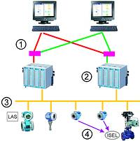
Having determined the advantages and limitations of control in the field, what about the fears? Every control engineer has his own particular horror scenarios, but some come up more often than others. It is part of the risk analysis to assess what action, if any, should be made in response to such situations, the result might be a system similar to that shown in Figure 3. In the following, four common fears have been selected, the consequences of each discussed and possible solutions presented.
Zombies
A device dies on me in the middle of the night. I lose the loop.
This can occur in any system. The actual consequences will depend on the role of the device in the control loop. With some roles, it is possible to design a recovery strategy, with others the device must be replaced.
1. When the device dies, function blocks awaiting input from the dead device will flag bad status, and the associated loops will assume the programmed fail-safe mode.
2. For devices providing input to a loop, it is possible to automatically recover to a redundant counterpart by using the input selector block.
3. Devices running control blocks must be replaced, because at the moment most host systems do not provide function block redundancy. The loop will flag bad status and any outputs will assume the programmed fail-safe mode. If the control block is in the actuator itself, the mechanical override of the valve will cause it to assume the fail-safe mode selected.
4. All function blocks used in the dead device must also be present in its replacement. If non-standard function blocks are in use, then the replacement device must correspond exactly to the dead one. Depending on the configuration tool, it is a simple matter to set up the new device and partially download the control strategy. The loop will then run again.
Godzilla
Something comes along and chews up the fieldbus cable to the controller: I lose the control in all the devices on the segment.
Cable breaks can occur in any system and the consequences are always that at least one loop is lost. What is quicker, to hook up the two bus wires or locate and repair an analogue connection?
1. Since power is normally lost, the mechanical override on the valves will cause them to move to the fail-safe position selected.
2. Since communication is lost, any loops in other segments requiring data from the affected devices will flag bad input status and default to the programmed fail-safe state.
3. If the loop was designed with power redundancy only, the back-up LAS will take over control, and all loops within the affected segment will function normally. External loops will react as in Item 2.
4. If power, controller (hardware) and control (application) redundancy has been provided, the back-up controller will take over control and all loops will act normally.
Psycho
The controller is taken out, I lose all control. In other systems yes, but with Foundation Fieldbus it depends on the control strategy you have selected. Assuming there are no function blocks being executed in the controller:
1. Normally, the back-up LAS in each segment will become active and all loops with in the connected segments will run normally (assuming there is still power). Any cross-segment loops will fail and default to the programmed fail-safe state.
2. If controller redundancy has been provided, the back-up controller will take over control and all loops will act normally.
1. If there are function blocks being executed in the controller:
2. Normally, the back-up LAS in each segment will become active and all loops within the connected segments will run normally (assuming there is still power) with the exception of those with blocks being executed in the controller. These, together with any cross-segment loops, will fail and default to the programmed fail-safe state.
3. If controller and control redundancy have been provided, the back-up controller will take over control and all loops will act normally.
Headless horseman
The HMI system goes. I am blind and have no idea what is going on.
If this has ever happened to you, then you will have provided a back-up system. High-speed Ethernet is part of the Foundation Fieldbus Specification, so depending on your control system, this does not have to be expensive, since components-off-the-shelf (COTS) can be used to support network redundancy.
1. Losing the HMI has no effect on the controller and devices: all loops will continue to work.
2. Providing that the OPC server is also redundant, if a back-up HMI is present, it will take over.
3. It is perfectly feasible to provide central or local emergency panels and buttons. FF function blocks include discrete inputs that allow manual override of critical loops, switching them to fail-safe mode.
This serialised paper is being printed with permission of the Fieldbus Foundation, the copyright holder.
For more information contact Grant Joyce, Endress + Hauser, 011 262 8000, [email protected]
| Tel: | +27 11 262 8000 |
| Email: | [email protected] |
| www: | www.endress.com |
| Articles: | More information and articles about Endress+Hauser South Africa |


© Technews Publishing (Pty) Ltd | All Rights Reserved
 printer friendly version