
In Part 4 it was pointed out that industry experts recommend loop equipment (including the control valve in question) be engineered so the process gain remains within the range of 0,5 to 2,0. This part continues looking at the factors that influence control response of the whole process.
Process optimisation requires a valve style and size be chosen that will keep the process gain within the selected gain limit range over the widest possible set of operating conditions. Because minimising process variability is so dependent on maintaining a uniform installed gain, the range over which a valve can operate within the acceptable gain specification limits is known as the control range of the valve.
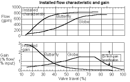
The control range of a valve varies dramatically with valve style. Figure 1 shows a line-size butterfly valve compared to a line-size globe valve. The globe valve has a much wider control range than the butterfly valve. Other valve styles, such as V-notch ball valves and eccentric plug valves generally fall somewhere between these two ranges. Because butterfly valves typically have the narrowest control range, they are generally best suited for fixed-load applications. In addition, they must be carefully sized for optimal performance at fixed loads.

If the inherent characteristic of a valve could be selected to exactly compensate for the system gain change with flow, one would expect the installed process gain (lower curve) to be essentially a straight line at a value of 1,0. Unfortunately, such a precise gain match is seldom possible due to the logistical limitations of providing an infinite variety of inherent valve trim characteristics. In addition, some valve styles, such as butterfly and ball valves, do not offer trim alternatives that allow easy change of the inherent valve characteristics.
This condition can be alleviated by changing the inherent characteristics of the valve assembly with non-linear cams in the feedback mechanism of the positioner. The non-linear feedback cam changes the relationship between the valve input signal and the valve stem position to achieve a desired inherent valve characteristic for the entire valve assembly, rather than simply relying upon a change in the design of the valve trim.
Although the use of positioner cams does affect modifying the valve characteristic - and can sometimes be useful, the effect of using characterised cams is limited in most cases. This is because the cam also dramatically changes the positioner loop gain, which severely limits the dynamic response of the positioner. Using cams to characterise the valve is usually not as effective as characterising the valve trim, but it is always better than no characterisation at all, which is often the only other choice with rotary valves.
Some electronic devices attempt to produce valve characterisation by electronically shaping the I/P positioner input signal ahead of the positioner loop. This technique recalibrates the valve input signal by taking the linear 4-20 mA controller signal and using a pre-programmed table of values to produce the valve input required to achieve the desired valve characteristic. This technique is sometimes referred to as forward path or set point characterisation.
Because this characterisation occurs outside the positioner feedback loop, this type of forward path or set point characterisation has an advantage over characterised positioner cams. It avoids the problem of changes in the positioner loop gain. This method, however, also has its dynamic limitations. For example, there can be places in a valve range where a 1,0% process signal change might be narrowed through this characterisation process to only a 0,1% signal change to the valve (that is, in the flat regions of the characterising curve). Many control valves are unable to respond to signal changes this small.
The best process performance occurs when the required flow characteristic is obtained through changes in the valve trim rather than through use of cams or other methods. Proper selection of a control valve designed to produce a reasonably linear installed flow characteristic over the operating range of the system is a critical step in ensuring optimum process performance.
Valve sizing
Oversizing of valves sometimes occurs when trying to optimise process performance through a reduction of process variability. This results from using line-size valves, especially with high-capacity rotary valves, as well as the conservative addition of multiple safety factors at different stages in the process design.
Oversizing the valve hurts process variability in two ways. First, the oversized valve puts too much gain in the valve, leaving less flexibility in adjusting the controller. Best performance results when most loop gain comes from the controller.
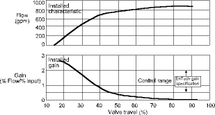
Notice in the gain curve of Figure 2 the process gain gets quite high in the region below about 25% valve travel. If the valve is oversized, making it more likely to operate in or near the region, this high gain can likely mean that the controller gain will need to be reduced to avoid instability problems with the loop. This, of course, will mean a penalty of increased process variability.
The second way oversized valves hurt process variability is that an oversized valve is likely to operate more frequently at lower valve openings where seal friction can be greater, particularly in rotary valves. Because an oversized valve produces a disproportionately large flow change for a given increment of valve travel, this phenomenon can greatly exaggerate the process variability associated with dead band due to friction.

Regardless of its actual inherent valve characteristic, a severely oversized valve tends to act more like a quick-opening valve, which results in high installed process gain in the lower lift regions (Figure 2). In addition, when the valve is oversized, the valve tends to reach system capacity at relatively low travel, making the flow curve flatten out at higher valve travels (Figure 2). For valve travels above about 50%, this valve has become totally ineffective for control purposes because the process gain in approaching zero and the valve must undergo wide changes in travel with very little resulting changes in flow. Consequently, there is little hope of achieving acceptable process variability in this region.
The valve shown in Figure 2 is totally misapplied in this application because it has such a narrow control range (approximately 25 to 45%). This situation came about because a line-sized butterfly valve was chosen, primarily due to its low cost, and no consideration was given to the lost profit that results from sacrificing process variability through poor dynamic performance of the control valve.
Unfortunately, this situation is often repeated. Process control studies show that, for some industries, the majority of valves currently in process control loops are oversized for the application. While it might seem counter-intuitive, it often makes economic sense to select a control valve for present conditions and then replace the valve when conditions change.
When selecting a valve, it is important to consider the valve style, inherent characteristic, and valve size that will provide the broadest possible control range for the application.
For more information contact Alpret Control Specialists, 011 249 6700, [email protected]
| Tel: | +27 11 249 6700 |
| Email: | [email protected] |
| www: | www.acs-autocon.com |
| Articles: | More information and articles about Automation Control Solutions |
© Technews Publishing (Pty) Ltd | All Rights Reserved