The basic objective of a company is to make a profit through the production of a quality product. A quality product conforms to a set of specifications. Any deviation from the established specification means lost profit due to excessive material use, reprocessing costs, or wasted product. Thus, a large financial impact is obtained through improving process control. Reducing process variability through better process control allows optimisation of the process and the production of products right the first time. A plant may have sound operational policies, with all the loss control in the world – but if the control valves are not operating soundly, efficiency will continue to suffer.
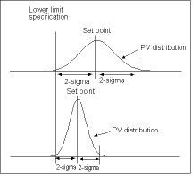
The non-uniformity inherent in raw materials and processes of production is a common cause of variation of the process variable both above and below the set point. A process that is in control, with only the common causes of variation present, typically follows a bell-shaped normal distribution (Figure 1).

A statistically derived band of values on this distribution, called the ±2sigma band, describes the spread of process variable deviations from the set point. This band is the variability of the process. It is a measure of how tightly the process is being controlled. Process variability is a precise measure of tightness of control and is expressed as a percentage of the set point.
If a product must meet a certain lower-limit specification, for example, the set point needs to be established at a 2sigma value above this lower limit. Doing so will ensure that all the product produced at values to the right of the lower limit will meet the quality specification.
The problem, however, is that money and resources are being wasted by making a large percentage of the product to a level much greater than required by the specification (see upper distribution in Figure 1). The most desirable solution is to reduce the spread of the deviation about the setpoint by going to a control valve that can produce a smaller sigma (see lower distribution in Figure 1).
Reducing process variability is a key to achieving business goals. Most companies realise this, and it is not uncommon for them to spend great sums of money on instrumentation to address the problem of process variability reduction. Unfortunately, the control valve is often overlooked in this effort because its impact on dynamic performance is not realised. Extensive studies of control loops indicate as many as 80% of the loops did not do an adequate job of reducing process variability. Furthermore, the control valve was found to be a major contributor to this problem for a variety of reasons.
To verify performance, manufacturers must test their products under dynamic process conditions. These are typically performed in a flow lab in actual closed-loop control. Evaluating control valve assemblies under closed-loop conditions provides the only true measure of variability performance. Closed-loop performance data proves significant reductions in process variability can be achieved by choosing the right control valve for the application.
The ability of control valves to reduce process variability depends upon many factors. More than one isolated parameter must be considered. Research within the industry has found the particular design features of the final control element, including the valve, actuator, and positioner, are very important in achieving good process control under dynamic conditions. Most importantly, the control valve assembly must be optimised or developed as a unit. Valve components not designed as a complete assembly typically do not yield the best dynamic performance. Some of the most important design considerations include:
* Dead band.
* Actuator/positioner design.
* Valve response time.
* Valve type and sizing.
Each of these design features will be considered in this series of articles to provide insight into what constitutes a superior valve design.
Dead band
Dead band is a major contributor to excess process variability, and control valve assemblies can be a primary source of dead band in an instrumentation loop due to a variety of causes such as friction, backlash, shaft wind-up, relay or spool valve dead zone, etc.
Dead band is a general phenomenon where a range or band of controller output (CO) values fails to produce a change in the measured process variable (PV) when the input signal reverses direction. When a load disturbance occurs, the process variable (PV) deviates from the setpoint. This deviation initiates a corrective action through the process. However, an initial change in controller output can produce no corresponding corrective change in the process variable. Only when the controller output has changed enough to progress through the dead band does a corresponding change in the process variable begin to occur. Any time the controller output reverses direction, the controller signal must pass through the dead band before any corrective change in the process variable will occur. The presence of dead band in the process ensures the process variable deviation from the setpoint will have to increase until it is big enough to get through the dead band. Only then can a corrective action occur.
Dead band has many causes, but friction and backlash in the control valve, along with shaft wind-up in rotary valves, and relay dead zone are some of the more common forms. Because most control actions for regulatory control consist of small changes (1% or less), a control valve with excessive dead band might not even respond to many of these small changes. A well-engineered valve should respond to signals of 1% or less to provide effective reduction in process variability. However, it is not uncommon for some valves to exhibit dead band as great as 5% or more. In a recent plant audit in the USA, 30% of the valves had dead bands in excess of 4%. Over 65% of the loops audited had dead bands greater than 2%.
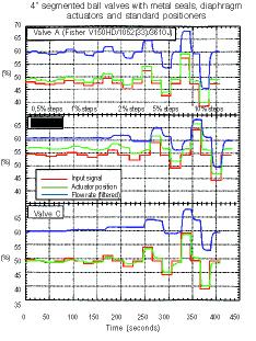
Figure 2 shows just how dramatic the combined effects of dead band can be. This diagram represents an open-loop test of three different control valves under normal process conditions. The valves are subjected to a series of step inputs that range from 0,5 to 10%. Step tests under flowing conditions such as these are essential because they allow the performance of the entire valve assembly to be evaluated, rather than just the valve actuator assembly - as would be the case under most bench test conditions.

Some performance tests on a valve assembly compare only the actuator stem travel versus the input signal. This is misleading because it ignores the performance of the valve itself. It is critical to measure dynamic performance of a valve under flowing conditions so the change in process variable can be compared to the change in valve assembly input signal. It matters little if only the valve stem changes in response to a change in valve input because if there is no corresponding change in the controlled variable, there will be no correction to the process variable.
In all three valve tests (Figure 2), the actuator stem motion changes fairly faithfully in response to the input signal changes. On the other hand, there is a dramatic difference in each of these valve's ability to change the flow in response to an input signal change.
For Valve A the process variable (flow rate) responds well to input signals as low as 0,5%. Valve B requires input signal changes as great as 5% before it begins responding faithfully to each of the input signal steps. Valve C is considerably worse, requiring signal changes as great as 10% before it begins to respond faithfully to each of the input signal steps. The ability of either Valve B or C to improve process variability is very poor.
Friction is a major cause of dead band in control valves. Rotary valves are often very susceptible to friction caused by the high seat loads required to obtain shut-off with some seal designs. Because of the high seal friction and poor drive train stiffness, the valve shaft winds up and does not translate motion to the control element. As a result, an improperly designed rotary valve can exhibit significant dead band that clearly has a detrimental effect on process variability.
Manufacturers usually lubricate rotary valve seals during manufacture, but after only a few hundred cycles this lubrication wears off. In addition, pressure-induced loads also cause seal wear. As a result, the valve friction can increase by 400% or more for some valve designs. This illustrates the misleading performance conclusions that can result from evaluating products using bench type data before the torque has stabilised. Valves B and C (Figure 2) show the devastating effect these higher friction torque factors can have on a valve's performance.
Packing friction is the primary source of friction in sliding stem valves. In these types of valves, the measured friction can vary significantly between valve styles and packing arrangements.
Actuator styles also have a profound impact on control valve assembly friction. Generally, spring-and-diaphragm actuators contribute less friction to the control valve assembly than piston actuators. An additional advantage of spring-and-diaphragm actuators is that their frictional characteristics are more uniform with age. Piston actuator friction will probably increase significantly with use, as guide surfaces and the O-rings wear, lubrication fails, and the elastomer degrades. Thus, to ensure continued good performance, maintenance is required more often for piston actuators than for spring-and-diaphragm actuators. If that maintenance is not performed, process variability can suffer dramatically without the operator's knowledge.
Backlash is the name given to slack, or looseness of a mechanical connection. This slack results in a discontinuity of motion when the device changes direction. Backlash commonly occurs in gear drives of various configurations. Rack-and-pinion actuators are particularly prone to dead band due to backlash. Some valve shaft connections also exhibit dead band effects. Spline connections generally have much less dead band than keyed shafts or double-D designs.
While friction can be reduced significantly through good valve design, it is a difficult phenomenon to eliminate entirely. A well-engineered control valve should be able to virtually eliminate dead band due to backlash and shaft wind-up. For best performance in reducing process variability, the total dead band for the entire valve assembly should be 1% or less. Ideally, it should be as low as 0,25%.
This article is adapted from the 'Fisher-Rosemount Control Valve Handbook'.
| Tel: | +27 11 249 6700 |
| Email: | [email protected] |
| www: | www.acs-autocon.com |
| Articles: | More information and articles about Automation Control Solutions |
© Technews Publishing (Pty) Ltd | All Rights Reserved