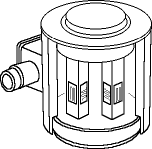
The heart of any modern weighing system is the load cell. Whilst they are not exciting to watch, load cells are highly accurate transducers, which provides the user with information not generally obtainable by other technology due to commercial factors.
In the first article of this series, we look at the construction of different load cell configurations and selecting the right configuration. Future articles will go into how to select the correct load capacity for an application, accuracy considerations, environmental protection, installation, lightning and internal protection, maintenance and a list of 'do's and don'ts'.
Load cells are designed to sense force or weight under a wide range of adverse conditions; they are not only the most essential part of an electronic weighing system, but also the most vulnerable. In order to get the most benefit from the load cell, the user must have a thorough understanding of the technology, construction and operation of this unique device. In addition, it is imperative that the user selects the correct load cell for the application and provides the necessary care for the load cell during its lifetime. Understanding these important issues and properly maintaining the load cells will ensure trouble free weighing for a long period of time.
Load cells may be damaged because of (shock) overloading, lightning strikes or heavy surges in current, chemical or moisture ingress, mishandling (dropping, lifting on cable, etc), vibration, seismic events or internal component malfunctioning. The do's and don'ts to be considered when using load cells will be mentioned in the final part of this series of articles.
Load cell selection
Load cell selection in the context of trouble free operation concerns itself primarily with the right capacity, accuracy class and environmental protection, rather then with a particular measuring principle like bending, shear, compression or ring torsion. While saying this, it should also be recognised that a particular measuring principle might offer distinct advantages in terms of overload capabilities or the ease of mounting. The different principles of operation will therefore be discussed:
Strain gauge load cells
In the case of strain gauge load cells, the sensing or spring element is the main structural component of the load cell. The element is designed in such a way that it develops a strain, directly proportional to the load applied. Sensing elements are normally made of high strength alloy steels (nickel-plated for environmental protection), precipitation - hardened stainless steels, heat treated aluminium alloys, or beryllium copper alloys. By bonding strain gages to a precisely machined element, the force applied can be identified in terms of resistance change. The strain gauges, usually four or a multiple of four, are connected in a Wheatstone bridge configuration in order to convert the very small change in resistance into a usable electrical signal. Passive components such as resistors and temperature dependent wires are used to compensate and calibrate the bridge output signal.
Bending load cells
These are sensing elements that are subjected to bending moments, widely used in many configurations for commercial transducers. Bending beams offer high strain levels at relatively low forces, which makes them ideal for low capacity load cells. Furthermore, in case of a beam with a symmetrical cross section about the bending axis, there are always two surfaces subjected to equal strains of opposite sign. This offers convenient means for implementing a full bridge circuit, while temperature compensation is relatively easy. Most products using the bending principle are of the parallelogram or double bending type. Revere Transducers' single point load cell type 642 is a straightforward parallelogram, while low capacity BSP, HPS and USP use this configuration but in a mechanically more complicated manner.

Bending as a measuring principle offers excellent linearity. Bending beams have relatively high strain levels with greater deflection compared to other measuring principles. This in turn means that although the cell is subjected to greater static overload, mechanical stops are more feasible. The dynamic overload capabilities are excellent because of the typical high deflection.
Shear load cells
Shear (beam) load cells have become increasingly popular for all types of medium and high capacity applications. Shear as a measuring principle offers a standard profile for a given capacity, good resistance against side loads and a relatively small sensitivity to the point of loading.

In Figure 2, at section A-A of the beam, a recess has been machined in each side, leaving a relatively thin web in the centre. Just as in a structural I-beam, most of the shear force imposed by the load is carried by the web, while the bending moment is resisted primarily by the flanges. At the neutral axis, where the bending stress is negligible, the state of stress on the web is one of pure shear, acting in the vertical and horizontal directions. As a result, the principle axis there are at 45° to the longitudinal axis of the beam, and the corresponding principal strains are of equal magnitude and opposite sign. Pairs of strain gages are installed on both sides of the web and connected in a full-bridge circuit for load measurement. Although it is more difficult to install the strain gages in a recess, they can readily be sealed and protected against environmental effects.
Shear-web sensing elements are not limited to beam configurations. Revere Transducers' higher capacity BSP and USP use this configuration in a more complicated manner. Low capacity shear load cells are difficult to produce, because they require a very thin web to obtain the necessary strain levels. High capacity shear load cells are usually based on dual shear webs in a beam configuration, as single-ended beams become expensive and cumbersome to mount. Shear beam load cells are relatively insensitive to the point of loading and offer a good resistance to side loads. This simplifies its use in many weighing applications. The overload capabilities are usually slightly better compared to bending beams, although mechanical stops are less feasible because of minimal deflection.
Compression load cells
Compression load cells can be based on shear, bending, ring torsion or column measurement. The column load cell has a history that dates back to the earliest strain gauge transducer. As indicated in Figure 3, the column element consists of one (single column) or more (multiple column) members. Although conceptually simple, the column element has a number of specific characteristics which makes these load cell types difficult to design and produce.
The column itself should be long enough, with respect to its cross section, to provide a uniform strain field, unaffected by end conditions. Since the column configuration is subject to second-order effects from off-axis or off-centre load components, provisions must be made to minimise these, for example by using two diaphragms at the upper end of the column. Column load cells are inherently non-linear due to the change in cross section, while deforming under load (Poisson's ratio). This non-linearity can be compensated for with semiconductor gauges, connected in the plus and minus excitation lines. The output of the semiconductor gauge thus serves as a feedback for adjusting the bridge voltage in the opposite direction to that of the non-linearity error.

Single column load cells become tall and difficult to handle (heavy), when designed for very high loads. Low profile canisters can be obtained if the load is carried by three or more columns, each column with its own set of gauges. The corresponding gauges from all of the columns are connected in series in the appropriate Wheatstone bridge arms. The result is not only an overall low profile, but also an improved performance when the cell is off-centre or off-axis loaded. Compression type load cells do not suffer from the momentum typically associated with beams. The ultimate overload capabilities are therefore excellent. However, the relatively small deflection makes these load cell types more sensitive to shock loading.
Ring torsion load cells
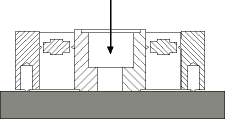
The ring torsion measuring principle is relatively new, and ideally suited for the capacity ranges which are typically served by shear and bending beams. Revere Transducers load cell model RLC is a low profile, stainless steel ring torsion load cell, based on a full bridge circuit of four circular strain gauges. The strain gauges are bonded to a ring-shaped part of the element that bends when load is introduced. This process causes a decrease of the ring diameter at the top, while the bottom experiences a diameter increase. Hence, two gauges are compressed and two gauges are in tension, when the unit is loaded. (See Figure 4)

The geometrical design of the sensing element provides enhanced specifications in terms of creep and hysteresis compared to shear and bending as a measuring principle. Due to its compression-loading mode, the unit does not suffer from the momentum typically associated with beams, and is therefore an inherently safer device, while maintaining a very low profile. Mechanical overload protection is established by the pre-determined distance between the load introduction ring and the base plate. Ring torsion load cells have a very low deflection, which makes them ideal for high-speed weighing, but they are also more sensitive to shock overloading.
The next article in this series will discuss capacity selection taking into consideration shock overload implications. Revere load cells are available from Instrotech.
| Tel: | +27 10 595 1831 |
| Email: | [email protected] |
| www: | www.instrotech.co.za |
| Articles: | More information and articles about Instrotech |

© Technews Publishing (Pty) Ltd | All Rights Reserved