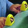

The original intent of two hand control systems is to protect the operators’ hands when loading and unloading parts into machines, such as presses, metal forming machines or guillotines.
Today, two-hand control systems protect operators by requiring:
1. A specific, deliberate operator action to start the machine cycle.
2. Continuous monitoring of the operator's hands during the dangerous machine motion.
The first two-hand control systems
With one early hand-protection method, the machine operator wore leather cuffs tethered with cords and pulleys to the machine-drive mechanism. This cuff system allowed the operator to load or unload parts while the machine was idle. When the machine started, the drive mechanism pulled the cord, pulling the operator's hands away from the machine's hazard point. While bothersome at best, the system was effective - if the operator wore the cuffs.

Later entered a more efficient method
This was a dual-push-button circuit (with a simple wiring of the buttons in series) that required the operator to push and hold both buttons throughout the machine cycle. Operators soon discovered, however, that they could 'tie down' one pushbutton and use the other button to re-initiate a machine cycle.
The unauthorised modification typically was an attempt to be more productive, especially if the operator's pay would be incentivised by the number of parts he would produce. While the 'tie-down' may have speeded the load-unload process, it also exposed the operator to serious hand injury - or worse.
Improvements to the early systems
In addition to the push-and-hold procedure, the next generation of two-hand control required both buttons to be released before another machine cycle could begin. This re-initiation circuit is used today. In addition, specifications for placing, orienting, and protecting the pushbuttons helped to prevent operators from using both pushbuttons with just one hand or a nearby tool. Pushbutton improvements led to palm buttons, which required less force to activate.
These advances helped to create a safer workplace, but left room for improvement in the areas of control circuit reliability and ergonomic design.

The first redundant, self-checking control modules
Earlier machine control designs consisted of relay logic elements that connected power to the machine drive motors or solenoid-controlled valves while the pushbuttons were pressed. These conventional control circuits usually could not detect failures that might cause an unintended machine cycle or that might allow the machine to continue operating after a hand was removed from a button. This key element - the ability to detect and reliably respond to such a failure - is the essence of a safe system.
In the late 1970s, Europe introduced a new, two-hand control module. It incorporated force-guided relay circuits that were redundant and self-checking that required the input signals from both pushbuttons to occur within 0,5 seconds. The force-guided relays were critical: They could detect an internal welded contact failure and respond by preventing another machine cycle from occurring. The module's redundant relay configuration ensured that if one relay failed, the other would back it up, preserving the safety function.
Not only could the circuit detect certain faults, its input simultaneity requirement ensured that the machine would not cycle without a deliberate operator action. It was only years later that North America adopted this safer, more reliable control idea.
Ergonomic considerations
Industrial ergonomic design became an issue in the early 1980s. The benefits associated with reduced physical stress and improved employee well-being were compelling factors for health agencies, insurance companies, unions and manufacturers.
Pushbuttons in use at that time required significant hand force to start and maintain a machine cycle. That, combined with the repetitive nature of the two-hand operation, caused a prevalent industrial problem: repetitive stress injury. The need for a better hand-activated device was evident.
Easier-to-activate electronic buttons entered the picture in the early 1990s. They required no hand force; an operator simply touched the sensing zone for the electronically controlled outputs to turn on. These touch buttons typically incorporated conventional, general-purpose circuitry and used photoelectric or capacitive sensing elements. Most manufacturers made no claim that their electronic buttons could detect safety-critical failures.
As the actuators become more ergonomic, they also become easier to defeat. So it is now more important for these easy-to-operate actuators to also incorporate self-checking technology, to maintain a high level of safety.
Self-checking actuating devices
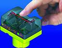
An innovative self-checking process has been devised for one new two-hand-control actuating device: Banner's STB. The 'Safety Touch Button' replaces traditional pushbuttons, where the operator only needs to put his finger or hand in the touch zone of the button. An infrared beam that 'looks' across this zone detects the finger or hand and activates the output circuit.
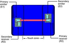
How is the self-checking achieved? After the devices power-up and initial system self-checking routines are conducted, the microcontrollers alternately activate the primary emitter (E1) to create a light pulse (see STB series optical paths). The light pulse travels across the button's touch zone. The primary receiver (R1) sees the light pulse if no obstruction blocks the beam and generates a signal in response.

E2 and R2 form a secondary emitter/receiver pair, which is used to 'test' the E1-R1 circuit. R2 looks for the beam from E1, while E2 sends a second beam to R1 a short time after E1 emits its beam. Because this secondary pair is an internally protected path it is used as the secondary safety circuit. If either the E1-to-R2 or the E2-to-R1 beam is not detected, the device's internal microcontrollers interpret this as a fault. This self-checking capability, together with the safety module, create a control-reliable system.
Fail-safe control reliability
The European Union has adapted safety standards over many years that describe, in detail, the concept and design features, usage and installation of safety components. The EN574 standard describes the functional aspects and principles for design, and the application of such devices on machines. It even defines its own set of two hand control device types. As such, if a particular machine has been identified as a risk level Category 4 (for example a press), it should be equipped with a two-hand control device meeting Type IIIC.
Banner Engineering's DUO-TOUCH SG kits are unique ergonomic style two hand control units that are certified by a notified body meeting the requirements of the Type IIIC as per EN574.
Need for additional guarding
A fail-safe control reliable two-hand control system can provide safe machine cycle control for operators, if installed correctly. However, the system cannot protect others who may be near the hazard point. This is a very real problem, and especially troublesome when a trainer, supervisor, or co-worker is directing or assisting an operator at the point of operation.
A single two-hand-control system can protect only one pair of hands. Additional safeguarding devices, such as safety light screens or a second two-hand-control system, can be used to protect additional personnel. This is a good practice to follow whenever more than one person might be exposed to the hazard point. The need to protect workers who routinely are exposed to industrial hazards is basic. It requires well-designed, properly installed equipment and a trained work force that can work safely. For these reasons, two-hand-control technology will continue to develop as the need grows for effective safety equipment.
Rodney Topham, RET Automation Controls
011 453 2468
| Tel: | +27 11 453 2468 |
| Email: | [email protected] |
| www: | www.turckbanner.co.za |
| Articles: | More information and articles about Turck Banner Southern Africa |
© Technews Publishing (Pty) Ltd | All Rights Reserved