

I often publish articles showing valve problems. One of the reasons is that I do not think many people understand that valves are generally responsible for 75-80% of all control loop problems. When it comes to relatively fast control loops, such as flow, valve problems can often be ‘got around’ as feedback control is so powerful, and provided the controller is well tuned, it often manages to overcome the valve problems.
Consider this example
A case in point was a splitter reflux flow control loop in a refinery, which had a really bad valve. The operators were battling to control it and had the loop in manual, but even then they found it extremely difficult to get the flow to reach stability at the correct value.
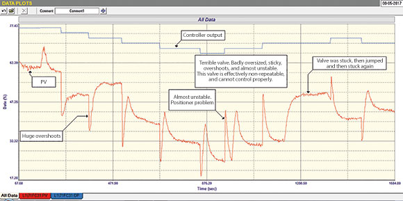
Figure 1 shows the open loop test. It is interesting because it shows so many problems with the valve:
• The valve overshoots hugely on closing and opening steps.
• It is terribly oversized, probably by as much as eight times, which magnifies by eight all the problems as seen on the PV.
• The positioner/valve combination is almost unstable and at times does go into a cycle.
• The valve sticks badly.
• The valve behaves differently on different steps, which means it is not repeatable.
When one encounters a control loop with a valve like this, you should know that it is not possible to get proper control, so it is essential that the valve be fixed or replaced as soon as possible. However, it is sometimes possible to get a measure of control in the setpoint region by deliberately tuning the controller with fast unstable parameters in order to make it cycle around setpoint. This can sometimes help keep the plant working until the valve can be fixed, which was done here and the resultant limited control cycle can be seen in Figure 2 – certainly not nice, but often better than no control at all.
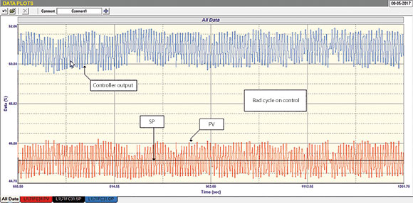
This solution should be used with caution, as cycling of this nature can sometimes cause problems with other interactive loops. However, if the flow loop is a cascade secondary to a slower loop, such as level or temperature, it will ensure that the average flow going into the process is correct, since the cycle is relatively fast.
Stick-slip cycles
The second example deals with a valve that exhibited a ‘stick-slip’ cycle.
Stick-slip cycles are one of the most misunderstood phenomena that occur on fast self-regulating processes such as flow loops, and are generally caused by valve or valve/positioner combination problems. On observing a stick-slip cycle, at least 95% of plant personnel are positive that it is a tuning problem and demand that the controller be retuned.
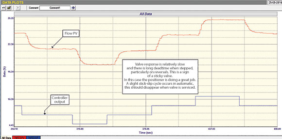
In this case, the tuning was pretty good and it took an open loop step test to analyse the problem with the valve – shown in Figure 3. On initial inspection it seems as if the valve is working perfectly, as it appears to follow step changes on the controller output very well. Deeper inspection shows that the valve is sticking quite badly though as it takes quite a few seconds to respond to the controller’s output steps. In particular, after one reversal in direction it took about seven seconds before it moved. This is far too long for a flow loop, which generally has deadtime of one, or at the most, two seconds. It is clear that the valve is sticking badly, and the positioner is doing a fantastic job of overcoming this and getting the valve smoothly to the correct position without overshoot.
Flow loops fall into the simplest class of process dynamics as they effectively can be defined as a self-regulating process with a single first order lag and deadtime. The correct pole cancellation to eliminate the process lag is to set the controller’s integral term equal to the time constant of the lag. Once that has been done, one merely has to adjust the controller’s proportional gain to get the control response desired for the particular loop.
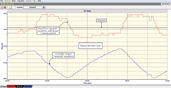
Typically, flow loops have lags of around one to two seconds, and similar deadtimes. Therefore, the controller typically needs to be tuned with an integral setting of 1-2 sec/repeat, which is relatively fast. So, if the valve sticks as in this case, then the integral term starts what is known as ‘winding up’, which means it sees a constant error and starts ramping up (or down) the controller output to try and get the valve to move. The result is an excess movement in the controller’s output in the form of a constant ramp. At the point where the valve moves, the output of the controller immediately starts heading in the opposite direction. The positioner sees that the controller’s output is asking for a certain valve position, and moves the valve to that position, but unfortunately that position takes the PV to the other side of setpoint as the controller’s output has moved too far.
The net result is a typical waveform with the controller’s output forming a saw-tooth, and the PV moving in close to a square wave pattern. These waveforms can be clearly seen in Figure 4.
Obviously one solution would be to slow down the integral. However, in real life it ends up in a term that is so slow that decent control response cannot be obtained. Although many people think that flow loops do not need to be controlled quickly, it must be noted that many of them are cascade secondaries, which are there to remove valve problems from the slower primary loop i.e. the secondary loop really needs to be as fast as possible. In cases like this, if the valve cannot be sorted out quickly, it is better to leave it with a stick-slip cycle as in many cases these are not actually a problem, since they are relatively slow and small and will not seriously affect the valve’s life, or cause process problems.

In cases where they can cause effects, like interaction, particularly when the valve is oversized, a good solution is to put a small band around setpoint, about the size of the amplitude of the stick-slip cycle, and slow the integral down in that band. This is an excellent solution where the flow loop is a cascade secondary.
As mentioned above, many people think the stick-slip cycle is a tuning problem and so detune the controller until the cycle stops. As discussed in a previous article, I think of a loop in manual as the ultimate slow tune. In general therefore, if you slow a loop down far enough it will stop cycling. I refer to this as ‘being tuned into manual’.
Michael Brown is a specialist in control loop optimisation with many years of experience in process control instrumentation. His main activities are consulting, and teaching practical control loop analysis and optimisation. He gives training courses which can be held in clients’ plants, where students can have the added benefit of practising on live loops. His work takes him to plants all over South Africa and also to other countries. He can be contacted at Michael Brown Control Engineering cc, +27 82 440 7790, [email protected], www.controlloop.co.za
| Email: | [email protected] |
| www: | www.controlloop.co.za |
| Articles: | More information and articles about Michael Brown Control Engineering |


© Technews Publishing (Pty) Ltd | All Rights Reserved
 printer friendly version