


In refineries, the process media flowing through valves are primarily liquids. With liquids, critical operating conditions caused by cavitation or flashing may occur. Symptoms are, for instance, increased noise emission, valve and pipe component erosion or low-frequency mechanical vibration in the valve and the connected pipeline. Under these conditions, in particular, neglecting details can result in negative influences on plant performance and costs of ownership. Unfortunately, common practice today is to select control valves in a ‘quick and dirty’ fashion, because the phases of planning, bidding and order processing are connected with significant pressures of cost and time.
This article presents the basic principles underlying these problems and shows how to eliminate them based on practical examples from refineries. A new throttling element is introduced, that is especially suited to reducing noise emission produced by cavitation. This new throttling element is being implemented in refineries with increasing success.
Typical refinery process conditions
Figure 1a illustrates normal refinery process data. A typical centrifugal pump with constant speed and normal pressure losses in the hydraulic system is characterised by the following:
Valve inlet pressure, p1, decreases as mass flow, W, increases, while valve outlet pressure, p2, increases. Vapour pressure, pv, depends on process medium temperature.
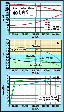
Flow conditions known as cavitation and flashing originate from vaporisation occurring in the throttling area. Cavitation occurs when the differential pressure ratio,
(according to IEC 60534-8-4), is higher than the valve's coefficient of incipient cavitation, xFz. Vapour bubbles are formed in the valve where they soon implode again because p2>pv. The cavitation index, σΓ, for incipient cavitation is equivalent to the reciprocal value of xFz. If p2 is lower than pv, flashing occurs and the vaporisation continues into the pipeline.
Figure 1b shows in accordance with Figure 1a that xF generally decreases as W increases. The three different areas of flow status in the valve are indicated by the following colours:
* Purely turbulent flow for xF<xFz (green area in Figure 1b).
* Cavitation for xF greater than and equal to xFz and xF<1 (light blue area in Figure 1b).
* Flashing for xF greater than and equal to 1 (yellow area in Figure 1b).
Vapour pressure, pv, in combination with operating pressures, p1 and p2, as well as the valve coefficient, xFz, determine if and when cavitation or flashing occurs. If the vapour pressure is relatively low, cavitation and noise emission will occur in the control valve at small-to-medium flowrates. For the lower vapour pressure value, pv = 49,6 kPa, cavitation does not occur between 82 000 and 102 000 kg/h; it does occur, though, when the flowrate is smaller than 82 000 kg/h (Figure 1b, green xF curve).
Consequently, flowrates between 102 000 and 65 770 kg/h induce a relatively high sound pressure level, Lpe,a, ie, between 80 and 88 dB(A) (Figure 1c, green Lpe,a, curve). For the higher vapour pressure value, pv = 290 psi, cavitation occurs when flowrate is in the upper range (Figure 1b, light blue xF curve). Flashing occurs below 82 000 kg/h. Since noise emission induced by cavitation is clearly higher than the noise emission induced by flashing, the valve is noisy at flowrates between 70 300 and 102 000 kg/h, reaching decibel levels from 85 to 93 dB(A) (Figure 1c, light blue Lpe,a curve).
To select a control valve suited to a particular application, and to evaluate flow conditions in as much detail as possible, knowledge of the exact process data is an absolute must. This is especially true for the actual pressure conditions downsteam of the valve. Extent of the pressure losses in pipes and elbows between the valve and, for example, a vessel at constant pressure, influences valve outlet pressure and, hence, flow status. Either flashing or cavitation can exist when the operating point is near the sharp transition from cavitation to flashing at xF = 1.
Cavitation and flashing
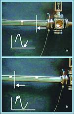
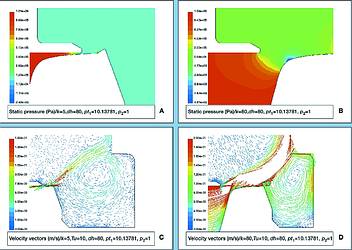
All examination of these phenomena is based on the variation of pressure and flow velocity in the main flow stream of the medium through the control valve (Figures 2a and b).
Cavitation
Since pressure difference at the control valve increases with p1 held constant, minimum pressure at the throttling area, generally referred to as vena contracta, vc, drops to the liquid vapour pressure, pv; for xF>xFz. Because p2>pv, vapour bubbles in the area at and around the throttling element collapse in the valve space downsteam of the vc. Figure 3a illustrates cavitation of the flow acting on the valve plug downsteam of the vc.
The following effects occur, depending on cavitation intensity:
* Noise emission due to cavitation with maximum values of 100 dB(A) (Figure 1c).
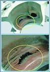
* Damage to valve components or pipeline due to cavitation erosion (Figure 5).
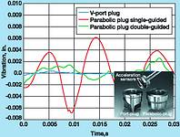
* Vibrational excitation of the throttling plug and entire valve (Figure 8).
* Choked flow which must be considered when calculating the Cv value.
Flashing
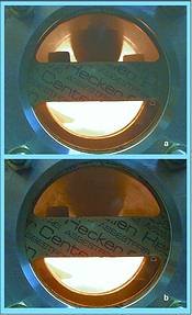
Cavitation ends and flashing starts when the pressure difference, p2-pv, becomes less than or equal to 0. Vapour bubbles in the two-phase flow that exit the valve do not implode, but remain intact (Figures 3b and 4a and b).
The result is a significantly reduced liquid/vapour mixture density on the downstream side of the valve compared to the valve inlet side (which is liquid phase only). This is linked to an increase in average flow velocity, which, in the case of flashing, is a multiple of the valve inlet velocity. In Figure 2b, for instance, outlet velocity is approx 40 m/s, which is clearly higher than the inlet velocity of 2 m/s. The higher the average flow velocity at the valve outlet, the higher the imbalance between the liquid and vapour phases. Figures 4a and b clearly show the propagating shock waves produced by the collapsing bubbles, whereby the entire pipeline system can be excited to mechanical or low-frequency vibration (<10 Hz).
In process applications with an inlet pressure that is just slightly higher than the vapour pressure, a two-phase liquid and vapour mixture is already present at the valve inlet. As a result, the described effects are even more intensified. Correspondingly, flashing, ie, true two-phase flow, may also cause great problems such as:
* Noise excitation, but at distinctively lower levels than those caused by intense cavitation (Figure 1c).
* Damage to valve components and pipelines caused by erosion due to liquid phase droplet impact, which can be further intensified by corrosive medium constituents.
* Vibration excitation of the entire pipeline due to shock waves propagating from the valve outlet, caused by the imbalance between the liquid and vapour phases (Figures 4a and b).
* Choked flow, and, in addition, substantially reduced flowrate in cases with two-phase flow at the valve inlet.
Measures against cavitation erosion
Erosion due to cavitation (Figure 5) is most likely to occur when flow is choked due to a high vapour bubble formation rate and when kinetic energy of the vapour bubbles swept away by the cavitating flow (Figure 3a) through the vc is high enough. The decisive parameters in the case of cavitation are the cavitation index, Kc, which corresponds to the differential pressure ratio at incipient choked flow, and the pressure differential, p1-p2, which is directly linked to kinetic energy of the cavitating flow.
In general, outlet velocity should be below 2,13 m/s and low-vibration valve plug designs should be used. Depending on valve trim design and material, a certain critical differential pressure value for significant cavitation damage, pcrit,cav, is allowable. Based on this, the following empirically gained values ('rules-of-thumb') can be stated to prevent difficulties caused by cavitation erosion (assuming no corrosive medium ingredients!):
* p1-p2<KC•(p1-pv): no problems.
* p1-p2 greater than and equal to KC•(p1-pv) and p1-p2<pcrit.cav (see Table 1): no problems.
* p1-p2 greater than and equal to KC•(p1-pv) and p1-p2>pcrit.cav (see Table 1): problems.
* p1-p2 greater than and equal to KC•(p1-pv) and p1-p2>4,48 MPa: multistage globe valve design recommended (eg, axial plug, Figure 6).
Measures against excessive noise emission caused by cavitation
If noise emission reduction requirements are very strict, the control valve must be selected so that xFz values (which depend on the valve stem position) are sufficiently high to fulfil existing process conditions, ie, xFz>xF.
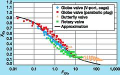
The KC value, as a measure for incipient choked flow, is essentially determined by valve design, ie, globe or butterfly valve. Additionally, xFz values are influenced by the special design and geometry of the throttling element. A variety of measurements showed that the valve's Reynolds number plays an important role. It is accounted for in the variable FxFz, as depicted in Figure 7, which is used to approximate xFz values for different valve types and sizes with one curve. The black curve represents a mean approximation which will also be part of the currently being revised IEC 534-8-4 standard at the suggestion of the author. From this, two fundamental tendencies can be derived as follows:
* As the Cv value rises, the xFz value decreases.
* As the valve style factor, Fd4, decreases, the xFz value rises.
Throttling element design details are expressed by the Fd value. The smaller the hydraulic diameter, the smaller this variable becomes. The smallest hydraulic diameters in the vc can be achieved with small annular gaps, while surface area of the throttling element remains the same compared to other vc geometries. Such geometries are found with parabolic plugs that have correspondingly a reduced rated Cv value and maximum possible seat diameter in the valve body.
Globe valves with a nominal size >2 inch with relative travels of 75% normally have xFz values between 0,2 and 0,35. Depending on the type of throttling element used, the xFz value increases more or less as relative travel percentage decreases. This is directly linked to a more or less decreasing Fd value.
Table 2 clearly shows that all plug types, except the parabolic, in typical refinery applications such as in Figures 1 and 2, can develop high-noise emission levels produced by cavitation at differential operating pressure ratios xF>0,5 to 0,8. Hence, parabolic plugs have a distinct advantage due to their higher xFz values when valve relative travel position is below 75%. The disadvantage that goes with it, however, is that occurrence of cavitation may cause strong mechanical vibration that could result in a torn-off plug when the plug stem is only single-guided in the top of the valve body. V-port plugs with asymmetrical orifice geometry show the least susceptibility to vibration (Figure 8). Similarly, cage-style valves and perforated plugs have a smaller tendency to vibrate. However, they have the disadvantage of being highly susceptible to contamination from particulate matter, resulting in fretting (holes or channels formed by erosion) and subsequent jamming problems.
Can the advantages of the individual plug types be combined so that noise levels produced by cavitation can be minimised?
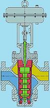
Figure 9 shows a new kind of throttling system that can be integrated in standard globe control valve bodies. This system has been optimised, using computational fluid dynamics (CFD) and performing a series of measurements. The system has the following properties:
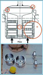
* Seat size is not reduced to attain the thinnest annulus between the seat and the plug. The result is a small hydraulic diameter and, therefore, small Fd factor, which has a positive effect on the xFz value. In addition, the longer 'throttling channel' causes pressure to decrease continuously (Figure 11a).
* To prevent mechanical vibration, the plug is double-guided in the body, and optimally in the seat, near the location where vibration is produced (Figure 9, circled letter A).
* The seat has a 'high seat joint' (seat/plug sealing surface Figure 9, circled letter B), which increases the xFz value for large valve plug openings because this has a positive effect on the vortex structure in the area below the plug (Figure 11d).
* The seat joint is cut back at the plug (Figure 9, circled letter C). This design increases the xFz value when the valve relative travel position is below 75%, because it has a positive effect on the vortex structure in the area above the plug (Figure 11c).
* Attenuation plates can be integrated in the seat below the plug. They increase the xFz value additionally when the valve-open position is over 75% (Figure 9, circled letter D). Additionally they further reduce noise level.
* The plug can also be designed as a pressure-balanced version - without a cage (instead with a 'hollow' skirt-shaped plug bored with small holes and sealed internally against an assembly fixed to the underside of the bonnet).
* For pressure differentials >1 MPa with severe cavitation (xF>KC), the plug or seat should be stellited or, better yet, precipitation-hardened carbide or martensitic steels.
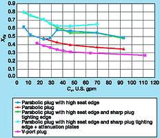
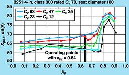
Based on the measured xFz value plots, Figure 10 clearly shows that such a system emanates noise produced by cavitation only at differential pressure ratios that are much higher than for V-port or piston-balanced cage-style plugs.
This new type of throttling element was used, for example, in a typical refinery application to adhere to the required sound level <70 dB(A) for the given operating points (Figure 12). This application in practice confirmed measurements made on the test bench.
In a different refinery, a rotary plug valve caused great noise and erosion problems at maximum valve inlet pressures p1 = 1,5 MPa and xF = 0,5-0,9. After 1½ years of operation, the valve body was eroded by cavitation (Figure 5, critical cavitation, see Table 1) and was replaced by the same rotary valve type. Valve body thickness of the new valve was checked by thermographic visualisation equipment in regular intervals by an independent consulting institute. After a further 1½ years and multiple valve investments, the rotary valve was replaced with a globe valve designed as described previously. This new valve successfully eliminated the problems in this case as well.
Measures against flashing
In case of flashing or two-phase flow, it is imperative that a sufficiently large nominal valve size be selected to limit average flow velocity on the downstream side of the valve, thus minimising the problems described in the section on cavitation and flashing. Experience shows that a maximum value of 200 fps should not be exceeded. For applications with active corrosive media, proper material selection additionally plays a significant role. Also, seat size should be reduced by at least one step to instantly provide as much space as possible for flow on the p2 side.
In a refinery, a 4 inch valve with the operating data described below caused significant problems: in the valve and in elbows upstream and downstream of the valve, erosion in combination with corrosion occurred. Evaluating existing operating data - including enthalpy data - showed that average outlet velocity at standard flowrate and approximately 13% vaporisation was approx 250 m/s. Therefore, wear caused by erosion due to droplet impact was practically inevitable. An additional disadvantage was installing the valve between two elbows within a short distance.
The problems were eliminated when an 8 in (~200 mm) valve featuring a low-vibration V-port plug with Cv 120 linear trim (Hastelloy trim chosen for corrosion resistance) was installed. The valve was centrally installed in the long pipeline upstream of the first elbow. Here, costs of ownership were 10 times higher than the first investment cost of the implemented valve.
At a different location in the same refinery, massive vibration problems resulted in cracking the pipeline supports. The originally-installed rotary plug valve was much too small (nominal size 805 mm). Resulting excessive flow velocities produced the flow conditions shown in Figures 4a and b, thus causing a strong vibrational pipeline excitation that was further intensified by the high-pressure recovery intrinsic to rotary plug valves. Installing a globe valve with a larger nominal size (508 mm) and a V-port plug solved this problem. Similar to the examples described previously, costs of ownership significantly added to the original investment cost, until a suitable valve solution was finally selected and installed.
For more information contact Monitor Instruments, 021 552 6088, fax: 021 551 2515, moninst@iafrica.com

Dr Jörg Kiesbauer is head of the 'Development Test Department' at Samson AG, Mess-und Regeltechnik, Frankfurt/Main, Germany. His work fields include R&D in control valves including accessories and self-operated regulators (flow capacity, sound emission, failure diagnostics, optimisation of prediction methods). Since 1999, Dr Kiesbauer has been a guest expert of IEC committee 65B WG 9.
| Tel: | +27 21 552 6088/9 |
| Fax: | +27 21 551 2515 |
| Email: | sales-za@samsongroup.com |
| www: | www.southafrica.samsongroup.com |
| Articles: | More information and articles about Samson Controls |


© Technews Publishing (Pty) Ltd | All Rights Reserved
 printer friendly version