A modern scada system often communicates directly with an OPC server which itself communicates with PLCs, RTUs, and/or Moxa ioLogik remote I/O units to pass sensor readings and control signals back and forth between the OPC server and devices.
Whereas the more traditional OPC DA server uses a polling method, which can use quite a bit of network bandwidth, the newer OPC UA server uses a ‘report by exception’ methodology to reduce the amount of information that the OPC server needs to send to the scada software. The combination of OPC UA with Moxa’s patented Active OPC server technology provides users with a seamless communication solution that can save an impressive amount of bandwidth.
In this white paper, we explain the difference between ‘updating data by polling’ and ‘updating data by exception’, give some general rules of thumb you can follow to decide which method is suitable for your various I/O devices, and introduce Moxa’s new MX-AOPC UA server solution.
Introduction
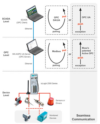
For more than half a century, scada systems have given operators located in a central control room the ability to monitor and control multitudes of devices spread out over a wide geographical area. The structure of a modern scada system, as depicted in Figure 1, has the scada software at the top, monitored devices at the bottom, and an OPC server in between. PLCs, RTUs, and/or Moxa ioLogik remote I/O units are used to pass sensor readings and control signals back and forth between the OPC server and devices. The PLC/RTU/ioLogik units provide the remote locations with a certain amount of autonomy, and are smart enough to implement local control schemes independent of the scada software itself.

Scada software and OPC servers have traditionally been based on a client-server polling model. That is, the scada software polls the OPC server, which itself polls the PLC/RTU/ioLogik for current sensor readings, and then the scada operator issues commands in response to whatever information is provided by the software’s user interface. Although some readings could be polled more or less frequently than other readings, sensors that monitor critical readings (eg, whether or not a locked door is open or closed) may need to be polled as frequently as once per second to give operators enough time to take the necessary action (e.g., alert security personnel), and to ensure that the scada system is properly notified. For example, if the door’s status is polled once every 5 seconds, but the door is opened and then closed within a 4-second time interval, the scada system won’t even know that the door was opened. If you only need to monitor the status of one door, then frequent polling may not be a problem. However, for scada systems that monitor the status of hundreds of doors, frequent polling of so many sensors could occupy a large amount of network bandwidth, and as a result slow down other applications that are connected to the same network.
About ten years ago, Moxa introduced its patented Active OPC concept, which is implemented by Moxa’s ioLogik products. Put simply, Active OPC gives dumb I/O devices the intelligence they need to initiate a connection with the OPC server. In other words, since the I/O devices are connected to the ioLogik via local serial connections, the ioLogik can poll these devices as frequently as it likes without putting any burden on the Ethernet network, and only sends readings to the OPC server (over the Ethernet network) when certain pre-configured conditions are met. As illustrated in Figure 1, the action of a traditional client-server polling model is sometimes described as a ‘pull’ (since the OPC server ‘pulls’ I/O readings out of the various devices), whereas the action of ioLogik’s Active OPC is described as a ‘push’ (since the ioLogik ‘pushes’ I/O readings from the various devices to the OPC server).
Updating data by polling or exception
For many years now ‘updating data by polling’ has been the industry standard for communication between the OPC server and OPC clients (i.e. scada software). Now, however, engineers can decide between updating data by polling and updating data by exception. Generally speaking, which option to choose depends on two factors: (1) the frequency with which sensor readings change, and (2) the urgency with which you need to know that a reading has changed. Sensor readings that change frequently need to be sampled frequently to get a true picture of how the sensor readings change with time. For sensor readings that don’t change very often, you could end up wasting quite a bit of network bandwidth if you sample too frequently. But, if you sample too infrequently, you might completely miss critical data (such as that a door has been opened and then closed). Let’s look in more detail at how updating works with an OPC UA server.
Updating data by exception
When configured for report by exception, an OPC UA server uses a ‘subscription and monitored item’ methodology in which a scada client subscribes to a set of monitored items. The OPC UA server samples the data points at regular ‘sampling intervals’, places the item’s readings in a queue, and then publishes the readings at regular ‘publishing intervals’. A critical aspect of this operation is that if a sampled reading has not changed compared to the previous sample, the reading is not placed in the queue. What this means is that readings that don’t change aren’t published, which is the essence of the ‘report by exception’ concept. Note, too, that OPC UA supports sending heartbeat signals during extended periods of inactivity so that each side of the connection will know that the other side is still alive, and consequently will not close the connection.
Two settings need to be configured on the OPC client to enable updating by exception: the sampling interval and the publishing interval. The sampling interval defines the rate at which the server checks for changes in the monitored device readings, and the publishing interval defines the rate at which the server sends notifications to the client. The sampling interval can be shorter than the publishing interval, in which case notifications are queued in the server until the publishing interval has elapsed. At that point, the server sends all of the notifications in the queue to the client.
With update by exception, since I/O readings are not transmitted when the monitored system’s status doesn’t change, operators can greatly reduce the amount of network bandwidth that’s required. This is especially true when the frequency of value changes is far less than the polling interval, such as is true when monitoring a door’s open/close status. Report by exception also saves computing resources on both server and client computers for hand-ling timeouts and retries.
Configuring easy-to-understand tag names
Most OPC servers require tag names to start with communication type, such as Ethernet or serial, followed by device name, followed by I/O point name. For example, a tag name for a pump’s on/off status might be Ethernet.Device.Pump_Status. However, since the location of the sensor the tag name is associated with is not included in the tag name, and since a single scada system might include thousands of tags, it is difficult or impossible for operators to determine which device is being referred to just by looking at the tag name. For this reason, tags are often associated with more detailed descriptions, with the tag names and descriptions organised in an Excel worksheet.
One way to get around this problem is to include the device’s location in the tag name by appending it to the device name. To illustrate, suppose the scada system uses the same model of I/O device to monitor two different pumps named PumpA and PumpB. If the two pumps are monitored by different I/O devices of the same model, you could write the tag names as Ethernet.Device_SiteA.Pump_Status and Ethernet.Device_SiteB.Pump_Status to differentiate between the two.
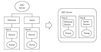
But why should tag names start with communication channel? If the tag names are based on the actual application architecture, it would be easier for users to construct the tag names. The difference in tag naming strategy is illustrated in Figure 2.

The diagram on the left is less intuitive, and could get rather messy since if Site A also uses serial devices, then Site A would also appear under the Serial branch. The diagram on the right shows the same system organised by the application architecture. In this case, all devices at Site A will appear under the Site A branch, and the tag names could be written as SiteA.Device.Pump_Status and SiteB.Device.Pump_Status. These tag names are more readable, and make it easier to configure your scada system.
OPC UA makes it easier to connect servers and clients
Configuring OPC to work between the server and the client on different computers was a real headache before the OPC unified architecture was available. For example, the user had to log in with the same account and password on both the server and client computers, which can be extremely inconvenient from a practical point of view. In addition, the user needed to follow detailed unintuitive step-by-step instructions to configure DCOM security.
In contrast, OPC UA uses an optimised TCP-based UA binary protocol for data exchange, in which communication can be activated by opening up a single user-configurable port in the firewall. Users can create many TCP URLs for OPC server endpoints, with each endpoint mapping to a unique port. OPC UA clients only need the URL of the server endpoint to connect to the OPC UA server.
Integrated security mechanisms such as X509 certificates ensure secure communication on the Internet. Users can define security policies such as ‘Sign and Encrypt’ between the OPC UA client and server. Users only need to import the client’s ‘Certificate Authority’ file from the OPC UA client and export the server’s Certificate Authority file to OPC UA clients to establish authority between the server and client. Then, the ‘Discover Servers’ function can be used in the OPC UA client to discover OPC UA servers accessible over the network. Finally, users can select the TCP URL to connect to the OPC UA server.
Moxa’s MX-AOPC UA server solution
MX-AOPC UA Server expands on Moxa’s patented ‘Active OPC’ monitoring technology, incorporates support for Modbus protocol, and provides a secure and reliable gateway between local devices and a remote scada system. Moxa pioneered ‘push type’ I/O processing (as opposed to ‘pull type’ or simply ‘polling’) in the automation industry with the release of its Active OPC Server. The patented MX-AOPC UA server offers both a polling and non-polling architecture alongside the standard OPC UA protocol, giving users the choice of pull or push-based communication with Moxa devices.
For more information contact RJ Connect, +27 (0)11 781 0777, [email protected], www.rjconnect.co.za
| Tel: | +27 11 781 0777 |
| Email: | [email protected] |
| www: | www.rjconnect.co.za |
| Articles: | More information and articles about RJ Connect |

© Technews Publishing (Pty) Ltd | All Rights Reserved